Edit a Virtual World
For information about opening a file in the editor, see Open the 3D World Editor.
For a step-by-step tutorial, see Build and Connect a Virtual World.
Add Objects
Add virtual world objects (for example, the wing of an airplane) by adding nodes in the tree structure pane. The hierarchy of nodes controls the scope to which node properties apply.
Note
Nodes must have unique names to work in the Simulink® 3D Animation™ product.
Approaches for Adding Objects
Use one of these approaches to add a node.
| Approach | Procedure |
|---|---|
| Use the Nodes menu |
|
| Use a context menu for a node |
|
| Insert an object from a library |
For For information about library objects, see 3D World Editor Library. |
| Add an inlined virtual world 3D file | For a |
The node that you add gets added to different locations in the hierarchy, depending on the node that you select to begin adding a node.
| Selected Node | Location of Added Node |
|---|---|
ROOT | At the bottom of the hierarchy |
Node at the next level down from the ROOT node (for example, a
Transform node). | Above the selected node |
A children node | Under the children node (as a child node of the selected
node) |
Copy and Paste a Node
You can copy a node below a top-level Transform node and paste that
copied node to be a child of another node, including the ROOT
node.
You can paste the copied node as either an explicit text copy (Paste) or as a referenced copy (Paste As Reference).
An explicit text copy allows you to edit properties of that node, independently from the original node that you copied.
A referenced copy node appears with the term
USE. Referenced copies streamline the tree structure pane display. Edits that you make to the original (referenced) node are applied to the copied node, ensuring that the two nodes remain exact copies of each other.
To copy and paste a node:
In the tree structure pane, select the node that you want to copy.
Copy the node, using one of these techniques:
Select Edit > Copy.
Right-click the node and select Copy.
Under the appropriate node, paste the copied node.
Paste the node using one of the following techniques:
Select the Edit > Paste or the Paste As Reference menu item.
Right-click the parent node and select Paste Node, and then select Paste or Paste As Reference.
Copy and Paste Between Virtual Worlds
In the same editing session, you can copy nodes from a virtual world in one virtual world 3D file to another virtual world in a different file. After you copy the nodes from one virtual world, select File > Open to open the second file where you want to paste the nodes.
Edit Object Properties
To define the characteristics of an object, in the tree structure pane, select the appropriate property. At the bottom of the 3D World Editor, use the object properties edit pane to change property values. Then click Apply.
The tree structure pane shows the current property values, which reflect your edits.
When you enter a numeric field value in the 3D World Editor, you can use MATLAB® expressions and MATLAB variables. For example, to convert an angle from degrees to radians, enter a
MATLAB expression such as 25*pi/180.
Set Viewpoint Values Using Camera Position
You can use the current camera position to specify interactively a viewpoint in the 3D World Editor.
Navigate to the position in the scene where you want the viewpoint.
In the tree structure pane, right-click a
Viewpointnode.Select Copy values from current camera.
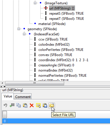
Specify a URL
For objects that have a URL field, to specify a URL, select the
node and use one of these approaches.
In the property edit box for the URL, enter the URL.
Select the 0 on the left side of the property edit box and click the Select File URL button. Navigate to the file.
Document a Virtual World Using Comments
To document a virtual world, in the object property edit pane, use the Comments tab for nodes and properties. Comments can help others understand the design of a virtual world.
Comments do not appear in the virtual world. They appear in the virtual world 3D file,
next to the given node or property, on lines that begin with #.
Display Event Fields
You can display eventIn and eventOut fields in the
3D World Editor tree pane. Either click the Show Events button
![]() or select Tree > Show Events.
or select Tree > Show Events.
You can perform an IS mapping for events in a
PROTO declaration.
Expand and Collapse Nodes
To expand a node in the tree structure pane, click the plus (+) sign to the left of the node. To collapse a node, click the minus (–) sign to the left of the node.
To expand or collapse all nodes in one step, select Tree > Expand All or Tree > Collapse All.
To expand subtrees within a node:
In the tree structure pane, right-click a node.
From the context menu, select Expand Subtree.
Alternative approaches for expanding the subtree for a node are:
Select Tree > Expand Subtree.
Click the
 button.
Hide Default Values
To simplify the tree view, you can hide default values. Select Tree > Hide Default Values. To display default values, clear the Hide Default Values option.
Highlight Nodes and Virtual World Objects
To select and highlight virtual world objects using the mouse pointer in the 3D World Editor view pane, use the select mode. Use that mode to highlight a node that defines a virtual world object or to highlight a virtual world object that a node defines. In the 3D World Editor display pane, the selected virtual world object is highlighted with an orange outline. For example:
Open a model with a 3D World Editor. Select File > Open in Editor.
openExample('CaptureaFigureExample')
vredit('vrpend.x3d')
In the 3D World Editor toolbar, click the
 button.
Tip
Alternatively, you can select the View Pane > Select menu item.
When the cursor hovers over a selectable object in the view pane, the cursor shape changes to a hand symbol.
In the virtual world display pane, click the yellow box.
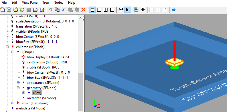
The corresponding
Shapenode in the tree structure pane is highlighted.In the tree structure pane, click in the
Rink (Transform)node, select the bottomShapenode. The rink is highlighted.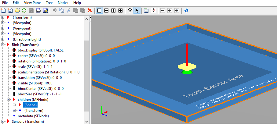
Tip
If you select a node in the tree structure pane but do not see anything highlighted in the virtual world display pane, adjust the viewing angle to make the highlighted object visible.
To return to navigation mode, in the 3D World Editor toolbar, click the
 button.
 Tip
Alternatively, you can select the View Pane > Navigate menu item.
You can use Shift-click to select multiple objects in the tree structure pane or view pane.
If you do not want objects to be highlighted when you pick them, in the display pane right-click and clear the Rendering > Highlight Selected Objects option. Alternatively, you can use the F4 key.
Note
Compound virtual world objects, such as objects defined using
Inline and PROTO nodes, are selected and
highlighted as a whole. You cannot select individual components of these objects.
Selection and Highlighting Preferences
By default, the cursor in view pane navigates in the virtual world. To have the mouse
cursor in the view pane behave in select mode by default, set the Simulink
3D Animation 3D World Editor preference View pane mouse behavior
preference to select. As an alternative, use the
DefaultEditorMouseBehavior parameter with the
vrsetpref command.
By default, virtual world objects are highlighted when you select them using select
mode. To have the default behavior for selected virtual world objects be to not highlight
the objects, set the Simulink
3D Animation 3D World Editor preference Highlight selected objects
preference to off. As an alternative, use the
DefaultEditorHighlighting parameter with the
vrsetpref command.
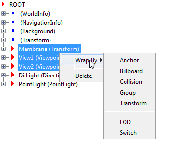
Wrap Nodes as Children of Another Node
To wrap contiguous nodes as children of another node:
Select the nodes. You can use the Shift key to select contiguous nodes, and the CTRL key to select discontiguous nodes.
Right-click the selected nodes and from the context menu, select Wrap By.
As an alternative, on the 3D World Editor menu bar, select Nodes > Wrap By.
From the list of nodes, select the node in which you want to wrap the selected nodes.
Remove Nodes
To delete one or more nodes, select the nodes and use one of these methods:
On the toolbar, click the red X button.
Click the Delete button.
Select Edit > Delete.
Right-click the node and select Delete.
From the Edit menu, you can also delete a specific child node or all the children nodes of a selected parent node, without deleting the parent node.
To cut a node and save it to the clipboard, select the node and use one of these techniques:
On the toolbar, click the scissors button.
Select Edit > Cut.
Right-click the node and select Cut.
Save and Export Virtual World 3D Files
You can save your virtual world files as virtual world using the File > Save or File > Save As menu items.
If you use the Save option, the 3D World Editor renames the
previous version of the file by appending .bak after the
.wrl, .x3dv, or .x3d
extension.
If you use the Save As option, the 3D World Editor saves the file using the new name that you specify. The file is saved in a form that the Simulink 3D Animation Viewer and 3D World Editor support (for example, the saved file preserves links to the library texture files).
Use the File > Export menu item to export a virtual world 3D file for use:
With other VRML or X3D tools
On different computers
In previous versions of the Simulink 3D Animation (previously the Virtual Reality Toolbox™) product (for VRML files)
Note
You cannot save an X3D file (.x3d or .x3dv) file
as a VRML (.wrl) file.
For exported files, the 3D World Editor copies referenced inlined virtual world 3D files
and texture files to the <filename>_files folder. It modifies the
corresponding URLs for those files, so that they point to the
<filename>_files folder.
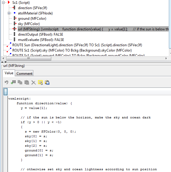
Edit VRML and X3D Scripts
To add a VRML or X3D Script node:
In the Tree structure pane, select the
ROOTnode.Select the appropriate type of script, using the Node > Add > Common > Script menu.
To add Script interface elements:
Right-click a
Scriptnode.Select the appropriate Add Interface Item menu option.
The following is an example of a Script node in the Tree
structure pane.
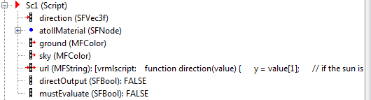
For a url node, click the node and either specify the path to a
JavaScript® file or enter the URL code in the Object property edit
pane.
See Also
Functions
Related Topics
Select a Web Site
Choose a web site to get translated content where available and see local events and offers. Based on your location, we recommend that you select: United States.
You can also select a web site from the following list
Americas
- América Latina (Español)
- Canada (English)
- United States (English)
Europe
- Belgium (English)
- Denmark (English)
- Deutschland (Deutsch)
- España (Español)
- Finland (English)
- France (Français)
- Ireland (English)
- Italia (Italiano)
- Luxembourg (English)
- Netherlands (English)
- Norway (English)
- Österreich (Deutsch)
- Portugal (English)
- Sweden (English)
- Switzerland
- United Kingdom (English)
Asia Pacific
- Australia (English)
- India (English)
- New Zealand (English)
- 中国
- 日本Japanese (日本語)
- 한국Korean (한국어)