Build and Connect a Virtual World
Introduction
This example shows you how to create a simple virtual world using the 3D World Editor. The example does not show everything that you can do with the editor. However, the example does show you how to perform some basic tasks to get started.
This example assumes that you have set your default editor to be the 3D World Editor. For details, see Set the Default Editor.
Define the Problem
Suppose that you want to simulate and visualize in virtual reality the deformation of a sphere. In your virtual world, you want to have two boxes representing rigid plates (B1, B2) and an elastic sphere (S) between them. All three of the objects are center-aligned along the x-axis. The boxes B1 and B2 move toward S with identical velocities, but they move in opposite directions. As they reach the sphere S, they start to deform it by reducing its x dimension and stretching both its y and z dimensions.
The following table lists the positions and dimensions of the objects that you create for this example.
| Object | Center Position | Dimensions |
|---|---|---|
|
|
|
|
|
|
|
|
|
The Simulink®
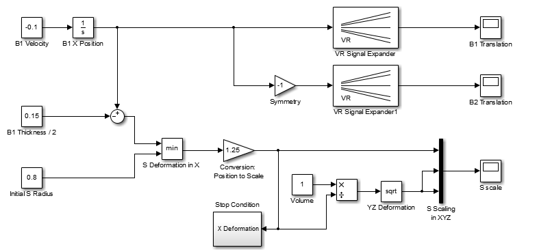
3D Animation™ product includes the tutorial model vrtut3. This simplified
model simulates the deformation of an elastic sphere. After collision with the rigid blocks,
the sphere's x dimension decreases by a factor from 1 to 0.4. Also, the
y and z dimensions expand to keep the volume of
the deformed sphere-ellipsoid constant. Additional blocks in the model supply the correctly
sized vectors to the Simulink
3D Animation block. The simulation stops when the sphere is deformed to 0.4 times its
original size in the x direction.
Your first task is to open a Simulink model and add a Simulink 3D Animation block to your model.
Open Tutorial Model Three
This example opens the tutorial model three, vrtut3, showing how to connect a Simulink® model to a virtual world.
open_system("vrtut3");Add a Simulink 3D Animation Block
This procedure uses the Simulink model vrtut3 to show how to add a Simulink
3D Animation block to your model. The model generates the values for the position of B1,
the position of B2, and the dimensions of S (as described in Define the Problem).
Open tutorial model three,
vrtut3.openExample('vrtut3');A Simulink window opens with a model that contains Simulink 3D Animation VR Signal Expander blocks, but no VR Sink block to write data from the model to Simulink 3D Animation. Instead, this model uses Scope blocks to monitor temporarily the relevant signals.
From the MATLAB® Command Window, type
vrlib
The Simulink 3D Animation library opens.
From the Library window, drag and drop the VR Sink block to the Simulink diagram. You can then close the Library Browser window.
Your next task is to create a virtual world that you will associate with the VR Sink block.
Add Nodes
Create Boxes
Defining virtual world objects involves defining a hierarchy of nodes. This example
shows how to define Transform nodes under the ROOT
node, with each Transform node including a hierarchy of
children, Shape, Appearance,
Geometry, and specific shape (in this case, a Box)
nodes.
In the tree in the left pane, click
ROOT(the topmost item).Add a
Transformnode, using the following sequence of menu selections.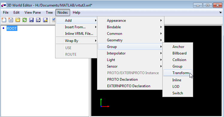
This
Transformnode is for the B1 box. To name theTransformnode:Right-click the
Transformnode.Select the Edit Name menu item.
In the edit box to the left of the
Transformnode, typeB1.
Add a
Shapenode:Expand the
B1 Transformnode.Select the
childrennode.Add a
Shapenode, using the following sequence of menu selections:
Add an
Appearancenode for the Shape node:Under the
Shapenode, select theappearance (SFNode)node.Add an
Appearancenode, using the following sequence of menu selections.
Add a
Materialnode to theAppearancenode:Expand the
(Appearance)node and select thematerial(SFNode)node.Add a
Materialnode, using the following sequence of menu selections.
Add a
Boxnode to thegeometrynode:Select the
geometry(SFNode)node of the(Shape)node.Add a
Boxnode, using the following sequence of menu selections.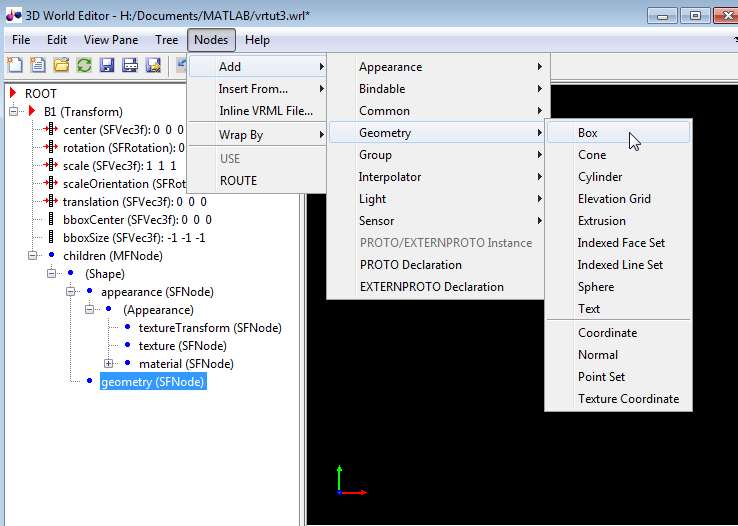
With all the nodes expanded, the 3D World Editor now displays a box in the virtual world display pane.
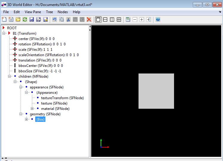
Make the box smaller by editing its
sizeproperty:Select the
sizeproperty of theBoxnode.In the object properties edit pane at the bottom of the 3D World Editor, enter
0.3in the first column, and1in the second and third columns.Click Apply.
The box becomes smaller.
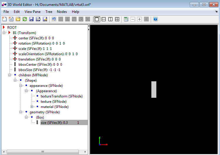
Move the box to the right by changing the
translation(SFVec3f)property of theB1(Transform)node. In the object properties edit pane, set the first column to3and leave the second and third columns set to0.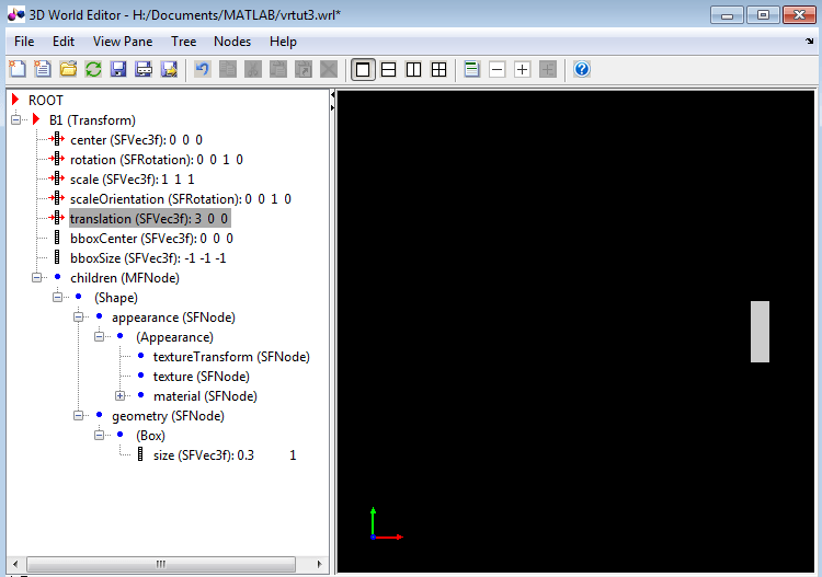
Add a second box that is similar to the first box.
Under the
ROOTnode, add aTransformnode (see step 2) and name itB2(see step 3).Copy the
Shapenode. Under theB1 Transformnode, right-click theShapenode in theB1 Transformnode and select the Copy menu item.Paste the copied Shape node into the
B2 Transformnode. Under theB2 Transformnode), right-click thechildrennode and select the Paste Node > Paste menu item.With the
B1node collapsed and theB2node expanded, the 3D World Editor looks like the following graphic.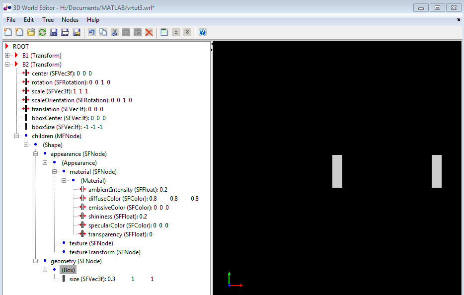
Move the box that you created to the left by changing the
translationproperty of theB2(Transform)node. In the object properties edit pane, set the first column to-3and leave the second and third columns set to0.
Create a Sphere
Your next task is to add a sphere between the two boxes. This section assumes that you have completed the tasks described in Add Nodes.
To make it easier to focus the tree structure pane on the nodes that you want to add, collapse the
B1(Transform)andB2(Transform)nodes.In the tree in the left pane, click
ROOTnode.Add a
Spherenode. The 3D World Editor includes a library of objects for building a virtual world, including aSphereobject.Add a
Spherelibrary object using the following sequence of menu selections.
From the list of Component Library folders, select the
Shapesfolder, and then select theSphere.x3dfile.Select the
Transformnode and name itS.With the
S Transformnode fully expanded and the otherTransformnodes collapsed, the 3D World Editor looks like the following graphic.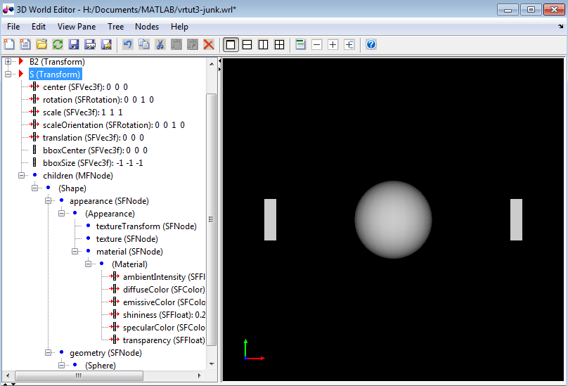
To make the sphere blue, under the
Materialnode, select thediffuseColorproperty. In the object properties edit pane, change the first column value to0.2, the second column to1, and the third column to1.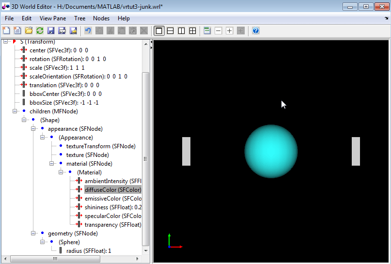
Save the virtual world file.
Your next task is to connect the model outputs to the Simulink 3D Animation block in your Simulink model. See Link to a Simulink Model.
Link to a Simulink Model
After you create a virtual world and a Simulink model with a VR Sink block, define the associations between the model signals and the virtual world.
Note
This procedure uses the model vrtut3 as an example. It assumes that
you have opened the model and that you have added a VR Sink block, and that you have
created a virtual world called vrtut3.x3d.
Open the VR Sink Block Parameters dialog box. In the Simulink Editor, double-click the VR Sink block.
Next to the Source file edit box, click Browse.
Select
vrtut3.x3d, and then click Open.In the Output pane, select Open Viewer automatically. This check box specifies that a viewer for the virtual world starts when you run the model.
For the Description parameter, type
vrtut3.In the VR Sink dialog box, click Apply.
In the tree structure pane, select the B1 translation, B2 translation, and S scale check boxes as the nodes that you want to connect to your model signals. Click OK.
The VR Sink block appears with corresponding inputs.
Delete the three Scope blocks and their associated input signal lines.
Connect the input lines from the two VR Signal Expander blocks and
S Scaling in XYZblock to the appropriate ports in the VR Sink block.
Double-click the VR Sink block.
The viewer appears.
In the viewer, select the Simulation > Block Parameters option. Your default viewer opens and displays the virtual world. For more information on changing your default viewer, see Set the Default Viewer.
In the VR Sink Block Parameters dialog box, click the View button.

In the Simulink Editor, select Simulation > Run.
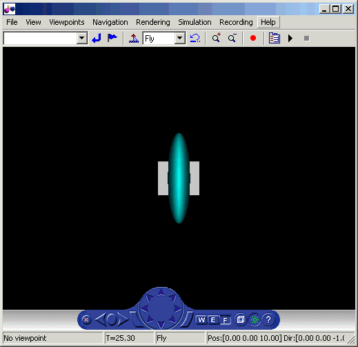
In your default viewer, you see a 3-D animation of the scene. Using the viewer controls, you can observe the action from various points.
When the width of the sphere is reduced to 0.4 of its original size, the simulation stops running.
See Also
Functions
vredit|vrlib|vrjoystick|vrspacemouse|vrgetpref|vrsetpref
