Create a Test File and Define the Test Interface (Tech Preview)
R2026bNote
The redesigned Simulink® Test Manager is a tech preview in R2026b. The primary purpose of the tech preview is to provide early access to the most common testing workflows. For more information about supported workflows, see Overview of the Redesigned Simulink Test Manager (Tech Preview).
To enable the feature, click the New Test Manager button in the
existing Test Manager or use the sltest.stmv2.open function at
the command line.
In this step, you create a test file and define the test interface by using the redesigned Simulink Test Manager. You create an SLTEST test file, define the component under test (CUT), and specify the parameters and signals that test cases in the test file can use.
Open the Model and Redesigned Test Manager
Open the example files, the sldemo_fuelsys_stm model, and the
redesigned Simulink Test
Manager.
openExample("simulinktest/TestManagerExample");sltest.stmv2.open;
Create a Test File and Define the CUT
In the redesigned Test Manager, you define tests in an SLTEST test file. In the test file, you specify the model and component you want to test.
Create a Test File Using the Redesigned Test Manager
Create an SLTEST file to test the
sldemo_fuelsys_stm model:
In the redesigned Test Manager, in the File section, select New > Test File.
In the New Test File dialog box, choose a location, enter the file name
fuelsys_stm, and click Save. The Test Manager displays thefuelsys_stmtest file in the Test Files pane. The test file contains three levels:Test file
Component under test
Test case
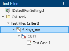
Specify the Model and Component Under Test
Next, specify the model sldemo_fuelsys_stm as the model and CUT:
In the fuelsys_stm tab, click the Select model button
 .
.In the Select model dialog box, click the Use currently open model button
 . Click OK.
In the Test Files pane, right-click CUT1 and select Rename. Enter
fuelsys_stm_CUT.
Click fuelsys_stm_CUT. In the fuelsys_stm_CUT tab, the Component Under Test section includes these fields:
Model
Component
Test Bench
By default, the Component and Test Bench are the top model.
Define the Test Interface
Use the Test Interface section to specify the inputs, parameters, and signals from the CUT that the test cases can use.
Specify Parameters in the CUT
To add parameters to the test interface:
Compile the model. In the Simulink toolstrip, in the Modeling tab, in the Compile section, click Update Model.
In the Test Interface section of the toolstrip, click Parameters.
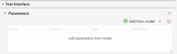
In the Parameters section, click Add from model.
In the
sldemo_fuelSys_stmmodel, click theEGO Fault Switchblock, and select ego_sw (model workspace).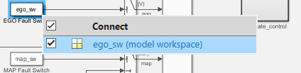
In the Add Parameters from Model dialog box, click Done.
Alternatively, you can add parameters by using the Model Data Table pane:
In the Parameters section, click Add from model > Open Model Data Table.
In the Model Data Table pane, select
map_swand click Add as Parameters.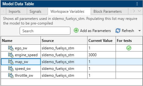
Specify Logged Signals in the CUT
To log signals during test execution:
In the Test Interface section of the toolstrip, click Signals.
In the Signals section, click Add from model > Open Model Data Table.
In the Model Data Table pane, set the drop-down list to
Show output signals.Select the
Gain1signal and click Log Signals.
In the next step, you modify the test interface and add a logical assessment to the test case. See Add a Logical Assessment to a Test Case and Review Results (Tech Preview).

