Convertidores (alta potencia)
Utilice estos ejemplos para aprender a modelar convertidores para aplicaciones de alta potencia (más de 48 V).
Ejemplos destacados
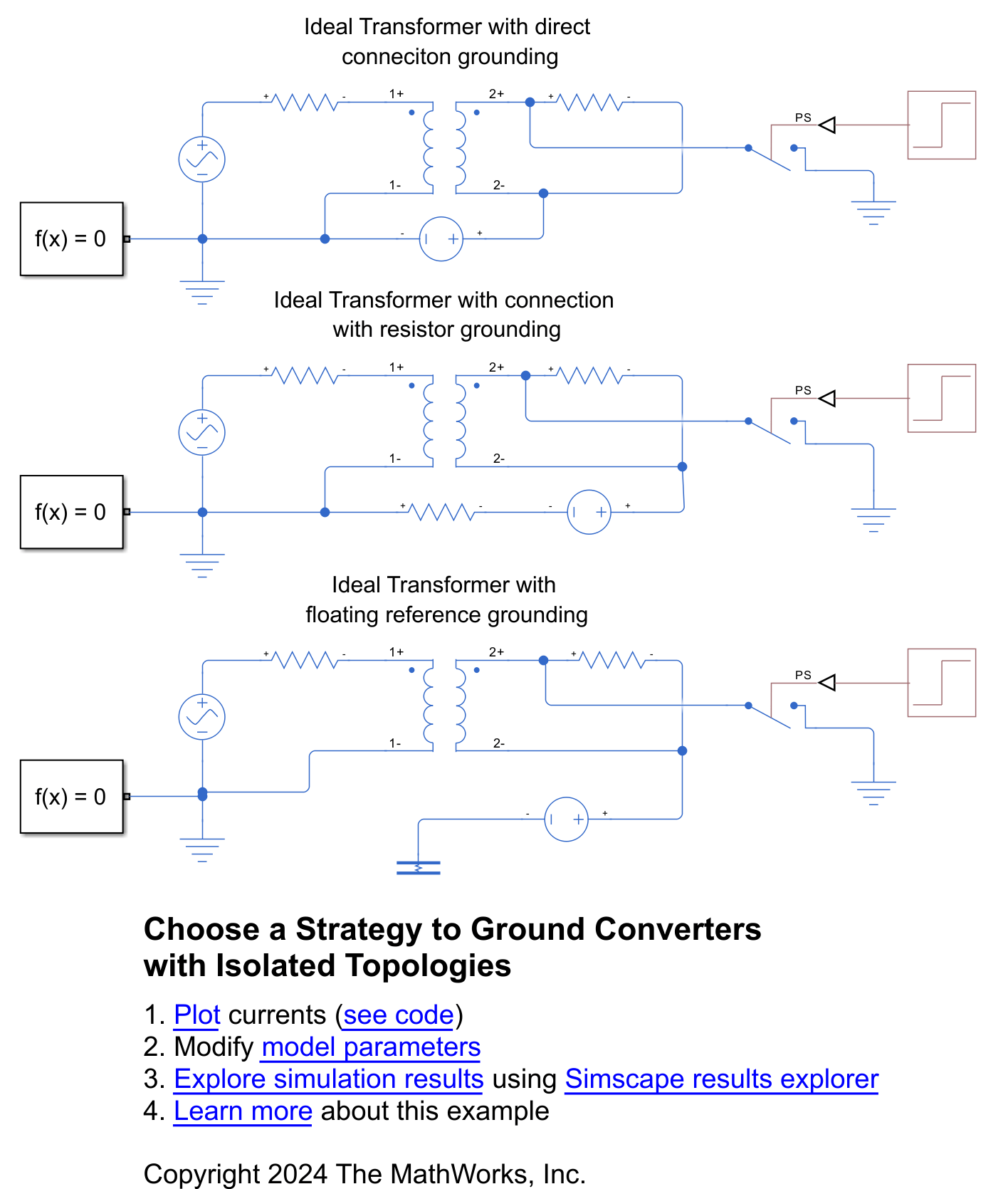
Choose Strategy to Ground Converters with Isolated Topologies
Correctly ground isolated topologies, such as electrical power converters with galvanic isolation. You compare three methods of grounding an ideal transformer and choose the best option depending on your application.
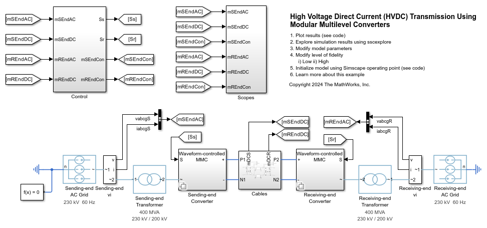
Model High-Voltage Direct-Current Transmission Using Modular Multilevel Converters
Models a high-voltage, direct-current (HVDC) transmission system using modular multilevel converters (MMC).

Model 18-Pulse Diode Rectifier
Model an 18-pulse diode rectifier to reduce the line current harmonics.

Model 24-Pulse Diode Rectifier
Model a 24-pulse diode rectifier to reduce the line current harmonics.

Power Factor Correction Rectifier Design
Convert a three-phase AC supply voltage into a stable DC bus voltage and control the reactive power drawn from the grid. To reduce the harmonics in the system, you use a PFC Rectifier Controller (Three-Phase) block to draw a sinusoidal current.

Composite Three-Phase Rectifier
This is the base model for analysis workflow examples.
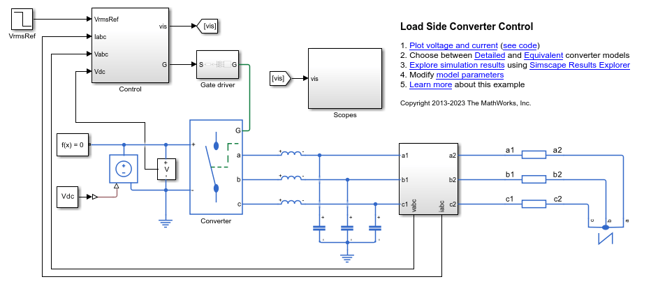
Load Side Converter Control
Control the RMS voltage in a load-side converter. The load is provided by a three-phase series RL element. The Control subsystem uses a PI-based cascade control structure with two control loops, an outer voltage control loop and an inner current control loop. The simulation uses step references. The Scopes subsystem contains scopes that allow you to see the simulation results.

Cicloconvertidor de puente trifásico
Este ejemplo muestra un cicloconvertidor de puente trifásico. El cicloconvertidor consta de 36 tiristores y tiene la capacidad de reducir la frecuencia de la tensión de entrada. El subsistema Control implementa el control de tensión RMS del cicloconvertidor. También proporciona generación de pulsos para la activación de los tiristores. El subsistema Visualization contiene scopes que permiten ver los resultados de simulación. El tiempo de la simulación, t, es 1 segundo. La carga aumenta cuando Load1 se activa en el instante t= 0,75 segundos.

Three-Phase Matrix Converter
A three-phase matrix converter that drives a static load and draws unity power factor at the source. The Scopes subsystem contains scopes that allow you to see the simulation results.

Three-Phase Modular Multilevel Converter
Control in open-loop a three-phase modular multilevel converter (MMC). Each MMC arm consists of four half-bridge submodules. A wye-connected series RLC structure provides the load to the system.

Three-Phase Voltage-Sourced Converter (FLB)
Model a three-phase voltage-sourced converter that uses Fixed Low-side Bias (FLB) modulation. This modulation scheme minimizes the switching in the converter as at any given time one phase is not being pulse modulated. The trade-off is the need for narrower pulses for a given level of acceptable harmonics. The model can be used to support selection of suitable values for L, C and the pulse modulation scheme parameters.

Three-Phase Voltage-Sourced Converter (SPWM)
Model a three-phase voltage-sourced converter that uses Sinusoidal Pulse-Width Modulation (SPWM). This modulation scheme compares a reference sine wave with a higher-frequency repeating triangle wave in order to generate the pulses. The model can be used to support selection of suitable values for L, C and the pulse modulation scheme parameters.

Rectificador basado en tiristor
Este ejemplo muestra un rectificador basado en tiristor.

Totem-Pole PFC
Control the rectified voltage in a totem-pole power factor correction (PFC) circuit. MOSFETs Q1 and Q2 form the 50 kHz fast switching leg. MOSFETs Q3 and Q4 form the line frequency slow switching leg. The control subsystem uses a PI-based cascade control structure. The Scopes subsystem contains scopes that allow you to see the simulation results.

Twelve-Pulse Thyristor Rectifier
Control a twelve-pulse thyristor rectifier. Two thyristor converters are connected to a Wye-Delta-Wye transformer on the input. A Thyristor 12-Pulse Generator block generates the gate signals for the two converters.

Vienna Rectifier Control
Control a Vienna rectifier. The Vienna rectifier subsystem consists of three-phase legs. Each leg has one power switch and six power diodes. The Control subsystem implements a closed-loop control strategy for the Vienna rectifier using space-vector modulation. Total simulation time is 0.1 s. At time 0.1 s, the Vienna Rectifier is engaged. At times 0.4 s and 0.6 s, the load steps up on the DC side.

Three-Phase Grid-Connected Rectifier Control
Control the DC-link voltage using a grid-connected rectifier. The Rectifier control subsystem uses a PI-based cascade control structure. The Scopes subsystem contains scopes that allow you to see the simulation results. If you have a license for HDL Coder™, you can generate VHDL code for an FPGA using the Simscape™ HDL Workflow Advisor.

Three-Phase Grid-Tied Inverter
Control the voltage in a grid-tied inverter system. The Voltage regulator subsystem implements the PI-based control strategy. The three-phase inverter is connected to the grid via a Circuit Breaker. The Circuit Breaker is open at the beginning of the simulation to allow synchronization. At time 0.15 seconds, the Circuit breaker closes, and the inverter is connected to the grid. The Scopes subsystem contains scopes that allow you to see the simulation results. The inverter is implemented using IGBTs. To speed up simulation, or for real-time deployment, the IGBTs can be replaced with Averaged Switches. In this way the gate signals can be averaged over a specified period or replaced with modulation waveforms.

Three-Phase Grid-Tied Inverter Optimal Current Control
Control the currents in a grid-tied inverter system. The Optimal controller subsystem implements an observer-based linear quadratic regulator strategy. To ensure zero steady state error, this example uses the observer as an alternative to the integral action. SPST switches connect the three-phase inverter to the grid. The switches are open at the beginning of the simulation to allow synchronization. At 0.15 seconds, the inverter is connected to the grid. Then, at 0.2 seconds the inverter increases the active power supplied to the grid. The Scopes subsystem contains scopes that allow you to see the simulation results. The inverter is implemented using Ideal Semiconductor Switch blocks. If you have a license for HDL Coder™, you can generate VHDL code for an FPGA using the Simscape™ HDL Workflow Advisor.

Control de tensión del inversor trifásico
Este ejemplo muestra cómo controlar la tensión en un sistema de inversor trifásico. El inversor se implementa utilizando IGBT. Para acelerar la simulación, o para el despliegue en tiempo real, los IGBT pueden reemplazarse por interruptores promediados. De esta forma, las señales de compuerta pueden promediarse en un periodo especificado o reemplazarse por formas de onda de modulación.

Three-Phase Matrix Converter with Venturini Modulation
Use Venturini modulation techniques to compute the duty cycles and logic statements of a three-phase matrix converter that drives a static load. The control subsystem implements three different modulation algorithms: Venturini modulation, third harmonic enhanced Venturini modulation, and third harmonic injection Venturini modulation with unity input displacement factor. The maximum voltage transfer ratio between input and output depends on the modulation technique and it is equal to either q=0.5 or q=0.866. The Scope blocks show the voltages and currents V_ABC, V_abc, I_ABC, and I_abc, where _UPPERCASE is used for inputs and _LOWERCASE for outputs.

Control de puente activo dual
Este ejemplo muestra cómo controlar la tensión de salida de un convertidor de CC-CC de puente activo dual. Cada interruptor está conectado durante el 50% del periodo de conmutación. Un controlador de desplazamiento de fase introduce un desplazamiento de fase variable en el puente de salida y controla la tensión de salida. La tensión de entrada y la carga del sistema se mantienen constantes a lo largo de la simulación. El tiempo total de la simulación (t) es 0,25 s. En el instante t= 0,15 s, la referencia de tensión cambia.

Microgrid with Electric Vehicles V2G (Vehicle-to-Grid) Support
Model a microgrid and how to regulate its frequency by using vehicle-to-grid (V2G) support from electric vehicles (EVs).

Manage Model Fidelity Using Variants
Compare and contrast modeling different fidelity levels by using variants. The controller model uses a Variant Source block configured in Expression mode. The plant model uses a Variant Subsystem.

Test Harness to Generate High-Power IGBT Device Characteristics
Provides test harness for estimating switching loss for different parameters of a N-Channel IGBT block.

Test Harness to Generate IV Characteristics of N-Channel IGBT
Provides test harness for estimating current-voltage characteristics of a N-Channel IGBT.

Three-Phase High-Power Converter Design and Analysis Workflow
The main steps involved in designing a high-power converter. High power converters are important building blocks for future electric mobility and microgrid solutions. To design a cost effective, lightweight, efficient converter, you must perform detailed analysis of different converter design options and deployment scenarios. This example helps you to simulate the steady state, transient electrical, and thermal characteristics of a three-phase two-level converter that uses Insulated-Gate Bipolar Transistor (IGBT) devices.

Fault Detection of Electric Vehicle Charger
Analyzes the fault of an electric vehicle (EV) charger using Simscape™ Electrical™ to model the grid, the converter, and its control unit. The reliability of these chargers is an important factor in their adoption. In this example, you use measurements from the grid and the DC side of the converter to detect a gate driver fault in the converter. To analyze and detect a fault, first you generate synthetic data for different conditions with and without faults. Then you use this data to train a classification algorithm using the Classification Learner (Statistics and Machine Learning Toolbox). Finally, you use the trained model to identify or detect faults in any phase and to generate the code for deployment on hardware. You can extend this model for other system level variations or noises by having a much larger and comprehensive training dataset.

Optimize Liquid Cooling System of Inverter
Analyze the performance of a liquid cooling system for a three-phase inverter. To find the steady-state temperatures and losses, you first run detailed and reduced order models (ROM). Then you compute the optimal size of the heatsink that maximizes the inverter efficiency and minimizes the lifetime cost.

High-Voltage, Direct-Current Transmission Using Voltage Source Converters
Models a high-voltage, direct-current (HVDC) transmission system using voltage source converters (VSCs).