Phase-Shifting Transformer
Libraries:
Simscape /
Electrical /
Passive /
Transformers
Description
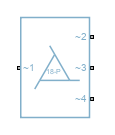
The Phase-Shifting Transformer block represents a 12-pulse, 18-pulse, 24-pulse, or 48-pulse phase-shifting transformer. Phase-shifting transformers are used in multi-pulse rectifiers in high-power and variable-load applications.
To select between a 12-pulse, 18-pulse, 24-pulse, or 48-pulse transformer, set the Number of pulses parameter to:
12-pulse— The transformer generates two different three-phase voltages with a phase shift of 30 degrees from each other.18-pulse— The transformer generates three different three-phase voltages with a phase shift of 20 degrees from each other.24-pulse— The transformer generates four different three-phase voltages with a phase shift of 15 degrees from each other.48-pulse— The transformer generates eight different three-phase voltages with a phase shift of 7.5 degrees from each other.
12-Pulse Transformer
Since R2024b
The 12-pulse transformer generates two different three-phase voltages with a 30 degree phase shift from each other at its secondary side:
The phase angle of the three-phase voltage at the ~2 port leads the phase angle of the three-phase voltage at the ~3 port by 30 degrees.
The phase angle of the three-phase voltage of the port at the primary side, ~1, lags the phase angle of the three-phase voltage at the ~2 port by 15 degrees.
18-Pulse Transformer
The 18-pulse transformer generates three different three-phase voltages with a 20 degree phase shift from each other at its secondary side:
The phase angle of the three-phase voltage at the ~2 port leads the phase angle of the three-phase voltage at the ~3 port by 20 degrees.
The phase angle of the three-phase voltage at the ~3 port leads the phase angle of the three-phase voltage at the ~4 port by 20 degrees.
The phase angle of the three-phase voltage at the ~3 port is the same as the phase angle of the three-phase voltage of the port at the primary side, ~1.
24-Pulse Transformer
The 24-pulse transformer generates four different three-phase voltages with a 15 degree phase shift from each other at its secondary side:
The phase angle of the three-phase voltage at the ~2 port leads the phase angle of the three-phase voltage at the ~3 port by 15 degrees.
The phase angle of the three-phase voltage at the ~3 port leads the phase angle of the three-phase voltage at the ~4 port by 15 degrees.
The phase angle of the three-phase voltage at the ~4 port leads the phase angle of the three-phase voltage at the ~5 port by 15 degrees.
The phase angle of the three-phase voltage of the port at the primary side, ~1, lags the phase angle of the three-phase voltage at the ~3 port by 7.5 degrees.
48-Pulse Transformer
Since R2024b
The 48-pulse transformer generates eight different three-phase voltages with a 7.5 degree phase shift from each other at its secondary side:
The phase angle of the three-phase voltage at the ~2 port leads the phase angle of the three-phase voltage at the ~3 port by 7.5 degrees.
The phase angle of the three-phase voltage at the ~3 port leads the phase angle of the three-phase voltage at the ~4 port by 7.5 degrees.
The phase angle of the three-phase voltage at the ~4 port leads the phase angle of the three-phase voltage at the ~5 port by 7.5 degrees.
The phase angle of the three-phase voltage at the ~5 port leads the phase angle of the three-phase voltage at the ~6 port by 7.5 degrees.
The phase angle of the three-phase voltage at the ~6 port leads the phase angle of the three-phase voltage at the ~7 port by 7.5 degrees.
The phase angle of the three-phase voltage at the ~7 port leads the phase angle of the three-phase voltage at the ~8 port by 7.5 degrees.
The phase angle of the three-phase voltage at the ~8 port leads the phase angle of the three-phase voltage at the ~9 port by 7.5 degrees.
The phase angle of the three-phase voltage of the port at the primary side, ~1, lags the phase angle of the three-phase voltage at the ~5 port by 3.75 degrees.
Variables
To set the priority and initial target values for the block variables before simulation, use the Initial Targets section in the block dialog box or Property Inspector. For more information, see Set Priority and Initial Target for Block Variables.
Nominal values provide a way to specify the expected magnitude of a variable in a model. Using system scaling based on nominal values increases the simulation robustness. You can specify nominal values using different sources, including the Nominal Values section in the block dialog box or Property Inspector. For more information, see System Scaling by Nominal Values.
Examples

Model 18-Pulse Diode Rectifier
Model an 18-pulse diode rectifier to reduce the line current harmonics.

Model 24-Pulse Diode Rectifier
Model a 24-pulse diode rectifier to reduce the line current harmonics.
Ports
Conserving
Parameters
References
[1] F. J. M. de Seixas and I. Barbi, A 12 kW three-phase low THD rectifier with high-frequency isolation and regulated DC output. IEEE Transactions on Power Electronics, vol. 19, no. 2, pp. 371-377, March 2004, doi: 10.1109/TPEL.2003.823201.
[2] Singh, Bhim & Gairola, S. A Zigzag Connected Auto-Transformer Based 24-Pulse AC-DC Converter. Journal of Electrical Engineering and Technology. 3. 235-242, 2008, 10.5370/JEET.2008.3.2.235.