Barometer
R2026bModel barometer sensor with measurement noise for UAV altitude estimation
Since R2025a
Barometer block
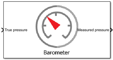
To add a block to a model, double-click the canvas and start typing the block name. Then, select the block from the list.
Libraries:
UAV Toolbox /
UAV Scenario and Sensor Modeling
Description
The Barometer block models a barometer sensor that adds measurement noise
to the true air pressure input. The noise consists of three additive components: a constant
bias offset, uncorrelated white Gaussian noise (scaled by the Noise
density parameter), and correlated noise modeled as a first-order autoregressive
process (controlled by the Bias instability and Decay
factor parameters) [1]. For the noise equations,
see Noise Model. Use this
block to simulate barometric pressure readings for UAV altitude estimation in the presence of
sensor noise. For MATLAB script-based workflows, use the barometerSensor
System object instead.
Examples
Open the barometerSimulation.slx Simulink model
open_system("barometerSimulation");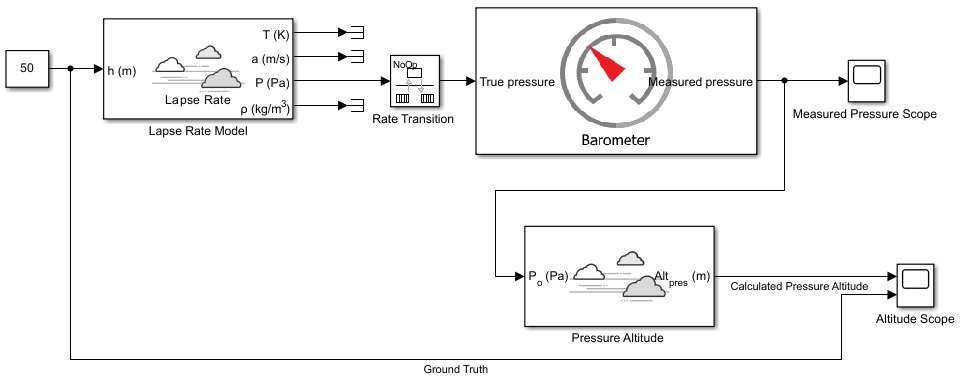
The model consists of the following blocks:
Lapse Rate Model (Aerospace Blockset) — Simulates lapse rate atmospheric model. The block receives altitude in meter, and outputs the atmospheric air pressure in Pascal, which is then measured by the barometer sensor. In this model, the input altitude is 50 meter.
Rate Transition — Simulates the discrete measurement of the Barometer sensor. In this model, the block is configured with a sample time of 0.1 second.
Barometer — Simulates a barometer sensor that generates air pressure reading in Pascal with a measurement noise that consists of constant measurement bias, uncorrelated white noise, and correlated noise.
Pressure Altitude (Aerospace Blockset) — Computes the altitude above mean sea level in meters based on the air pressure reading.
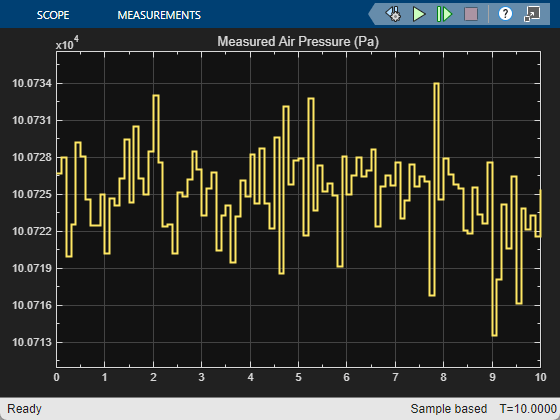
Measured Pressure Scope — Visualizes the pressure reading.
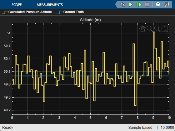
Altitude Scope — Visualizes the computed altitude above mean sea level and ground truth.
Run the model, and then open scope blocks to see the simulation results.
Ports
Input
Output
Parameters
Tips
To configure the block for a specific barometer sensor, obtain these values from the sensor datasheet:
Set Noise density to the sensor noise spectral density (typically listed in Pa/√Hz or equivalent units on the datasheet).
Set Bias instability to the long-term bias stability specification.
Set Decay factor to a value near 1 (such as 0.99) for sensors with slow-drifting bias. Use a smaller value for sensors with faster-varying bias.
Set Constant bias to 0 for a calibrated sensor, or to the expected residual offset.
Algorithms
References
[1] Sabatini, A.M., and V. Genovese. “A Stochastic Approach to Noise Modeling for Barometric Altimeters.” Sensors 13 (November 2013): 15692-15707. https://doi.org/10.3390/s131115692
Version History
Introduced in R2025a

