Generate HDL Code
R2026bAfter you verify the simulation behavior of your hardware model, generate an HDL IP core and integrate it with the SDR reference design. For the full workflow, see Target NI USRP Radios Workflow.
HDL Coder™ generates a reusable IP core module from your Simulink® model. A reference design integrates the IP core into the radio hardware. To generate the IP core:
Configure the output options. For details, see Configure Output Options.
Configure the HDL code generation settings. For details, see Configure HDL Code Generation Settings.
Map DUT ports to the reference design target interfaces. For details, see Map Target Interfaces.
After you complete these steps, you can generate a standalone IP core, or proceed to Generate Bitstream and Program FPGA, which handles IP core generation automatically as part of the bitstream build.
Configure Output Options
The workflow uses the HDL Code tab on the Simulink Toolstrip to access the HDL code generation options and start code generation. The Simulink Toolstrip contains contextual tabs that appear only when you need to access them. To access the HDL Code tab, open the HDL Coder app from the Apps tab on the Simulink Toolstrip.

In the Output options, select IP Core.
Make sure that the user logic subsystem in your model, the design under test (DUT), is pinned in the Generate Code options. To pin this selection, select the DUT in your Simulink model and click the pin icon.
Configure HDL Code Generation Settings
Open the Configuration Parameters window by clicking Settings in the HDL Code tab.
Navigate to the HDL Code Generation pane.
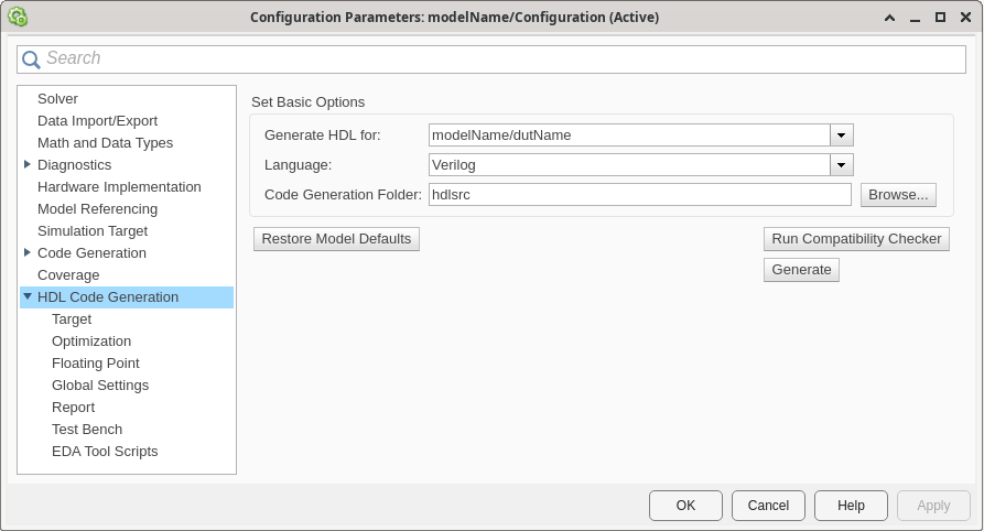
Configure the basic options with these settings.
| Parameter | Description | Value | Notes |
|---|---|---|---|
| Generate HDL for | Select the subsystem or model for which HDL code is generated. | Path to top level subsystem in root model | The list includes the path to the root model and to subsystems in the model. The default is the top level subsystem in the root model. |
| Language | Specify the HDL code generation language. | Verilog (default) | The generated HDL code complies with the Verilog-2001 (IEEE® 1364-2001) standard. Verilog is the only supported language for this workflow. |
| Code Generation Folder | Specify the target folder for the generated HDL code. | prj/hdlsrc (default) | The default target folder is a subfolder of your working folder, named
hdlsrc. |
Navigate to the Target pane.

Configure the Target settings according to your requirements.
Workflow Settings
| Parameter | Description | Value | Notes |
|---|---|---|---|
| Workflow | Specify the target workflow. | IP Core Generation (default) | The setting for this parameter determines the available parameters in the Target pane. |
| Project Folder | Specify the folder for workflow-specific files. | ' ' (default) | The software stores any created files in this folder, such as the generated IP core or synthesis tool project files. It places the generated HDL code in the folder specified by Code Generation Folder. |
Tool and Device Settings
| Parameter | Description | Value | Notes |
|---|---|---|---|
| Target Platform | Select the target platform for the generated HDL code. |
| For more information, see Supported Radio Devices. |
| Synthesis Tool | Select the synthesis tool for targeting the generated HDL code. | Xilinx Vivado | For more information about the installation requirements, see Install Vivado and Apply Patch. |
Reference Design Settings
| Parameter | Description | Value | Notes | |
|---|---|---|---|---|
| Reference Design | Specify the reference FPGA image for your design (since R2025a). |
| Options available when Target Platform =
USRP E320. Select the option that
corresponds to the Ethernet connection you have set up between the host and your
radio. For more information about setting up a USRP™ E320 radio for 10 Gigabit Ethernet, see Set Up USRP E320 Radio for 10 Gigabit Ethernet. | |
| Option when Target Platform = USRP
N310 | USRP N320 | USRP N321 | USRP
X310. | |||
| Option when Target Platform = USRP
X410. | |||
| Reference Design Tool Version | Specify the Synthesis Tool version. |
| Family, Device,
Package, and Speed are populated with
default values for this tool version. | |
| Reference Design Parameters | Daughterboard (since R2026a) | Specify the daughterboard type on the USRP X310 radio. | UBX-160 (default) | USRP X310 radio is configured with UBX 160 daughterboards. |
OBX-160 | USRP X310 radio is configured with OBX 160 daughterboards. | |||
TwinRX | USRP X310 radio is configured with TwinRX daughterboards. | |||
| Number of Input Streams | Specify the number of data streaming input ports on the DUT. | Positive integer | N/A | |
| Number of Output Streams | Specify the number of data streaming output ports on the DUT. | Positive integer | N/A | |
| Sample Rate | Specify the baseband sample rate in S/s. | Positive numeric scalar | The value can be any supported master clock rate (MCR) value divided by any supported interpolation or decimation factor. For details, see DUT Clock Frequency and Sample Rate. You
can update the sample rate after deployment using the | |
Reference Design Optimization (since R2026a) | Specify the level of optimization of reference design resources. The level you choose determines how much flexibility you have at run-time. Lower levels of optimization increase the overhead associated with the reference design, which can contribute to complex designs failing to meet timing constraints. For more information, see Reduce Resource Utilization and Achieve Timing Closure. | None | Maintain maximum flexibility at run-time:
| |
Moderate | Remove some run-time flexibility but maintain full debugging capability:
| |||
High | Remove some run-time flexibility but maintain some debugging capability:
| |||
Maximum | Remove run-time flexibility and debugging capability:
| |||
DUT Clock Source (since R2024b) | Specify the clock source for the DUT. | Radio (default) | The DUT is clocked at the MCR selected for the specified sample rate. For more information, see Radio Clock Source. | |
Custom | You can specify a user-defined DUT clock frequency with the Target Frequency parameter. Selecting this option generates a custom clock for your DUT using the Vivado® Clocking Wizard. For more information, see Custom DUT Clock Source. | |||
| Stream Port FIFO Length | Specify the buffer length in samples for each DUT input and output data streaming port. | Auto (default) | The software calculates the buffer length based on the target frequency and the maximum valid MCR of the radio. | |
Integer in the range 8 to 2048 | The buffer length is set to the specified value. | |||
| Register Port FIFO Length | Specify the buffer length in samples for each DUT register port. | Auto (default) | The software calculates the buffer length based on the target frequency and the maximum valid MCR of the radio. | |
Integer in the range 8 to 2048 | The buffer length is set to the specified value. | |||
Objectives Settings
| Parameter | Description | Value | Notes | ||||||||||
|---|---|---|---|---|---|---|---|---|---|---|---|---|---|
| Target Frequency | Specify the DUT clock frequency for HDL synthesis. | Maximum MCR of the target radio device (default) | If DUT Clock Source is set to
| ||||||||||
Positive numeric scalar (since R2024b) | If DUT Clock Source is set
to The valid range depends on the radio.
For more information, see Custom DUT Clock Source. |
Map Target Interfaces
Use the IP Core editor to map the DUT ports to IP core interfaces. Open the Interface Mapping table by clicking Target Interface in the HDL Code tab.
To compile your model and populate the table with your user logic, click the Reload IP
core settings button:  . If you make changes to your model, use this button again to repopulate
the DUT ports and their data types.
. If you make changes to your model, use this button again to repopulate
the DUT ports and their data types.

For each DUT port, manually assign the target interface from the Interface column dropdown.
The Interface Mapping column is populated automatically based on
the signal names in your model. For example, a port named Data_In is
assigned as Data in the Interface Mapping column. If
the mapping is incorrect, manually adjust the Interface Mapping
column.
When you have populated the table, validate the interface mapping by clicking the
Validate IP core settings button:  .
.
Map Register Interfaces
Assign any register input as a Write Register and any register
output as a Read Register.
Map Data Streaming Inputs
For each DUT port that corresponds to the first data
streaming input, populate the Interface column with Stream
Port Input0 (since R2026b). For each consecutive data streaming input, increment
the appended number. For example, assign each DUT port that corresponds to the fourth data
streaming input as Stream Port Input3.
For each data streaming interface, populate the Interface Mapping column with these values:
DataValidLastReadyEoB (optional)HasTime (optional)TimeStamp (optional)
The non-optional values must be assigned for every interface. For more information about how to configure data streaming interfaces in your DUT model, see Streaming Interface Guidelines.
For each data streaming input port, Data, open the Set Interface
Options window by clicking Options. Assign a source connection from
the following options.
| Source Connection | Description |
|---|---|
Antenna string that corresponds to a capture antenna on the radio, for
example, RF0:RX2 | The streaming input port receives samples from the specified radio antenna. If the Reference Design
Optimization parameter is set to |
Host | The streaming input port receives samples from the host. |
PL DDR Buffer | The streaming input port receives samples from the host through the PL DDR buffer, which ensures contiguous samples. This connection
counts toward the total number of PL DDR buffer connections available on your
radio, along with any other streaming interfaces mapped to |
In the Set Interface Options window, assign the stream buffer size as a number of samples, where each sample is 4 bytes. The stream buffer is an endpoint buffer on the FPGA that provides flow control between RFNoC blocks. The default is the maximum possible size (32768 samples), which is appropriate for most designs. To free FPGA block RAM for your DUT logic, reduce the buffer size to a smaller power of two.
Map Data Streaming Outputs
For each DUT port that corresponds to the first data
streaming output, populate the Interface column with
Stream Port Output0 (since R2026b). For each consecutive data streaming
output, increment the appended number. For example, assign each DUT port that corresponds
to the fourth data streaming output as Stream Port Output3.
For each data streaming interface, populate the Interface Mapping column with these values:
DataValidLastReadyEoB (optional)HasTime (optional)TimeStamp (optional)
The non-optional values must be assigned for every interface. For more information about how to configure data streaming interfaces in your DUT model, see Streaming Interface Guidelines.
For each data streaming output, open the Set Interface Options window by clicking Options. Assign a sink connection from the following options.
| Sink Connection | Description |
|---|---|
Antenna string that corresponds to a transmit antenna on the radio, for
example, RF0:TX/RX | The streaming output port sends data to the radio front end for transmission using the specified radio antenna. If the
Reference Design Optimization parameter is set to
|
Host | The streaming output port sends samples to the host. |
PL DDR Buffer | The streaming output port sends samples to the host through the PL DDR buffer, which ensures contiguous samples. This connection
counts toward the total number of PL DDR buffer connections available on your
radio, along with any other streaming interfaces mapped to |
Leave Ports Unmapped
To keep a port in your model without creating an interface
for it on the IP core, set the Interface column to No
Interface Specified (since R2026b). The port is not connected to any external
interface on the generated IP core. Use this option for ports, such as debug or diagnostic
ports, that you do not need exposed in the deployed design.
Configure IP Core Name
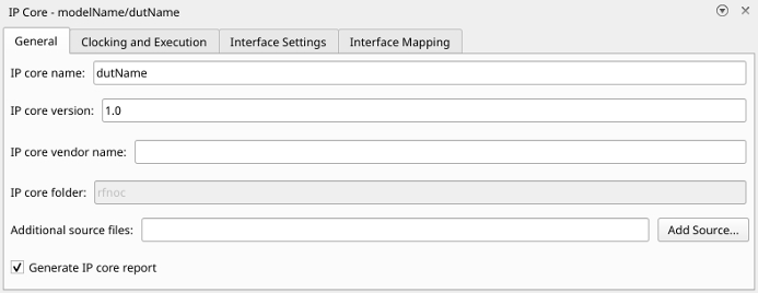
In the IP Core editor, navigate to the General tab. Ensure that IP core name contains only alphanumeric characters (since R2026a).
Generate IP Core
Note
This step is handled automatically in Generate Bitstream and Program FPGA. Use this step to generate the IP core files without building a bitstream.
To generate an IP core for your user logic without building a bitstream, in the
HDL Code tab, click Generate IP Core. This
generates an RFNoC compatible IP core that you can integrate into a design outside of
MATLAB® and Simulink. The IP core files are generated in a folder named rfnoc
within the project folder that you set up in the Configure HDL Code Generation Settings step.

