Main Content

wlanTGaxChannel

Filter signal through 802.11ax multipath fading channel

Description

The wlanTGaxChannel System object™ filters an input signal through an 802.11ax™ (TGax) indoor MIMO channel as specified in [1], following the MIMO modeling approach described in [4].

The fading processing assumes the same parameters for all NT-by-NR links of the TGax channel, where NT is the number of transmit antennas and NR is the number of receive antennas. Each link comprises all multipaths for that link.

To filter an input signal using a TGax multipath fading channel:

  1. Create the wlanTGaxChannel object and set its properties.

  2. Call the object with arguments, as if it were a function.

To learn more about how System objects work, see What Are System Objects?

Creation

Description

example

tgax = wlanTGaxChannel creates a TGax channel System object, tgax. This object filters a real or complex input signal through the TGax channel to obtain the channel-impaired signal.

tgax = wlanTGaxChannel(Name,Value) creates a TGax channel object, tgax, and sets properties using one or more name-value pairs. Enclose each property name in quotes. For example, wlanTGaxChannel('NumReceiveAntennas',2,'SampleRate',10e6) creates a TGax channel with two receive antennas and a 10 MHz sample rate.

Properties

expand all

Unless otherwise indicated, properties are nontunable, which means you cannot change their values after calling the object. Objects lock when you call them, and the release function unlocks them.

If a property is tunable, you can change its value at any time.

For more information on changing property values, see System Design in MATLAB Using System Objects.

Sample rate of the input signal in Hz, specified as a positive scalar.

Data Types: double

Delay profile model, specified as 'Model-A', 'Model-B', 'Model-C', 'Model-D', 'Model-E', or 'Model-F'.

The table summarizes the models properties before the bandwidth reduction factor.

ParameterModel
ABCDEF
Breakpoint distance (m)555102030
RMS delay spread (ns)0153050100150
Maximum delay (ns)0802003907301050
Rician K-factor (dB)000366
Number of taps1914181818
Number of clusters122346

The number of clusters represents the number of independently modeled propagation paths.

Data Types: char | string

Channel bandwidth, specified as one of these values.

  • 'CBW20' — Channel bandwidth of 20 MHz

  • 'CBW40' — Channel bandwidth of 40 MHz

  • 'CBW80' — Channel bandwidth of 80 MHz

  • 'CBW160' — Channel bandwidth of 160 MHz

  • 'CBW320' — Channel bandwidth of 320 MHz

Data Types: char | string

RF carrier frequency, in Hz, specified as a positive scalar.

Data Types: double

Speed of the scatterers, in km/h, specified as a positive scalar.

Data Types: double

Distance between the transmitter and receiver in meters, specified as a positive scalar.

TransmitReceiveDistance is used to compute the path loss, and to determine whether the channel has a line of sight (LOS) or non line of sight (NLOS) condition. The path loss and standard deviation of shadow fading loss depend on the separation between the transmitter and the receiver.

Data Types: double

Normalize path gains, specified as a numeric or logical 1 (true) or 0 (false). To normalize the fading processes such that the total power of the path gains, averaged over time, is 0 dB, set this property to 1 (true). Otherwise, set this property to false.

Data Types: logical

User index, specified as a nonnegative integer. If the property is set to 0, the angles of arrival and departure from the TGn channel model are used in the calculation of the spatial correlation matrix. If the property is set to a positive integer, pseudorandom offsets are applied to the TGn angles of arrival and departure before the calculation of the spatial correlation matrix. For more details, see the section on MIMO Enhancements.

Data Types: double

Transmission direction of the active link, specified as either 'Downlink' or 'Uplink'. The default value, 'Downlink', specifies transmission from an access point to a user station.

Data Types: char | string

Number of transmit antennas, specified as a positive integer.

Data Types: double

Distance between transmit antenna elements, specified as a positive scalar expressed in wavelengths.

TransmitAntennaSpacing supports uniform linear arrays only.

Dependencies

To enable this property, set the NumTransmitAntennas property to a value greater than 1.

Data Types: double

Number of receive antennas, specified as a positive integer.

Data Types: double

Distance between receive antenna elements, specified as a positive scalar expressed in wavelengths.

ReceiveAntennaSpacing supports uniform linear arrays only.

Dependencies

To enable this property, set the NumReceiveAntennas property to a value greater than 1.

Data Types: double

Large-scale fading effects applied in the channel, specified as 'None', 'Pathloss', 'Shadowing', or 'Pathloss and shadowing'.

Data Types: char | string

Number of building floors between the transmitter and the receiver, specified as a positive integer. Use this property in multiple floor scenarios to account for the floor attenuation loss in the path loss calculation. The default is 0, which represents a communication link between a transmitter and a receiver located on the same floor.

Dependencies

The NumPenetratedFloors property applies only when DelayProfile is 'Model-A' or 'Model-B'.

Data Types: double

Number of walls between the transmitter and receiver, specified as a positive integer. Use this property to account for the wall penetration loss in the path loss calculation.

The default is 0, which represents a communication link between a transmitter and a receiver without wall penetration loss.

Data Types: double

Penetration loss of a single wall in dB, specified as a real scalar.

Dependencies

The WallPenetrationLoss property applies only when NumPenetratedWalls is greater than 0.

Data Types: double

Fluorescent effect, specified as a numeric or logical 1 (true) or 0 (false). To include Doppler effects from fluorescent lighting, set this property to 1 (true).

Dependencies

To enable this property, set the DelayProfile property to 'Model-D' or 'Model-E'.

Data Types: logical

Power line frequency in Hz, specified as '50Hz' or '60Hz'.

The power line frequency is 60 Hz in the United States and 50 Hz in Europe.

Dependencies

To enable this property, set the FluorescentEffect property to 1 (true) and the DelayProfile property to 'Model-D' or 'Model-E'.

Data Types: char | string

Normalize channel outputs by the number of receive antennas, specified as a numeric or logical 1 (true) or 0 (false).

Data Types: logical

Enable channel filtering, specified as a numeric or logical 1 (true) or 0 (false). To enable channel filtering, set this property to 1 (true). To disable channel filtering, set this property to 0 (false).

Note

If you set this property to 0 (false), the step object function does not accept an input signal. In this case, the NumSamples and SampleRate properties determine the duration of the fading process realization.

Data Types: logical

Number of time-domain samples used to get path gain samples, specified as a positive integer.

Dependencies

To enable this property, set the ChannelFiltering property to 0 (false).

Data Types: double

Data type of impaired signal, specified as one of these values:

  • 'double' – Return the pathGains output as a double-precision matrix

  • 'single' – Return the pathGains output as a single-precision matrix

Dependencies

To enable this property, set the ChannelFiltering property to 0 (false).

Data Types: char | string

Source of random number stream, specified as 'Global stream' or 'mt19937ar with seed'.

If you set this property to 'Global stream', the current global random number stream is used for random number generation. In this case, the reset function resets the filters and creates a new channel realization.

If you set this property to 'mt19937ar with seed', the mt19937ar algorithm generates random numbers. In this case, the reset function also reinitializes the random number stream to the value of the Seed property.

Note

The random numbers of the channel components are distributed as follows:

  • The random phase of the Doppler component due to fluorescent lights is uniformly distributed. See equation 27 of TGn Channel Models for more information.

  • In multi-user scenarios using the TGac, TGah, or TGax channel models, the per-user angle-of-arrival (AoA) and angle-of-departure (AoD) rotations discussed in the MIMO Enhancements section are uniformly distributed.

  • The fading samples are generated from a normally-distributed complex uncorrelated Gaussian process with zero mean and unit variance in discrete time.

Data Types: char | string

Initial seed of an mt19937ar random number stream, specified as a nonnegative integer. The Seed property reinitializes the mt19937ar random number stream in the reset function.

Dependencies

To enable this property, set the RandomStream property to 'mt19937ar with seed'.

Data Types: double

Enable path gain output computation, specified as a numeric or logical 1 (true) or 0 (false).

Data Types: logical

Usage

Description

example

y = tgax(x) filters input signal x through the TGax fading channel defined by the wlanTGaxChannel System object, tgax, and returns the result in y.

example

[y,pathGains] = tgax(x) also returns in pathGains the TGax channel path gains of the underlying fading process.

This syntax applies when you set the PathGainsOutputPort property of tgax to 1 (true).

pathGains = tgax(x) returns the path gains. The NumSamples property determines the duration of the fading process.

This syntax applies when you set the ChannelFiltering property to 0 (false).

Input Arguments

expand all

Input signal, specified as a real or complex NS-by-NT matrix, where:

  • NS is the number of samples.

  • NT is the number of transmit antennas and must be equal to the NumTransmitAntennas property value of tgax.

Data Types: single | double
Complex Number Support: Yes

Output Arguments

expand all

Output signal, returned as an NS-by-NR complex matrix, where:

  • NS is the number of samples.

  • NR is the number of receive antennas and is equal to the NumReceiveAntennas property value of tgax.

Data Types: single | double

Path gains of the fading process, returned as an NS-by-NP-by-NT-by-NR complex array, where:

  • NS is the number of samples.

  • NP is the number of resolvable paths, that is, the number of paths defined for the case specified by the DelayProfile property.

  • NT is the number of transmit antennas and is equal to the NumTransmitAntennas property value of tgax.

  • NR is the number of receive antennas and is equal to the NumReceiveAntennas property value of tgax.

Data Types: single | double

Object Functions

To use an object function, specify the System object as the first input argument. For example, to release system resources of a System object named obj, use this syntax:

release(obj)

expand all

infoCharacteristic information about multipath fading channels
stepRun System object algorithm
releaseRelease resources and allow changes to System object property values and input characteristics
resetReset internal states of System object

Note

reset: If the RandomStream property of the System object is set to 'Global stream', the reset function resets the filters only. If you set RandomStream to 'mt19937ar with seed', the reset function also reinitializes the random number stream to the value of the Seed property.

Examples

collapse all

Obtain a channel impulse response by filtering an impulse through a TGax channel.

Create an impulse.

input = zeros(100,1);
input(10) = 1;

Create the TGax channel System Object with path loss and shadowing, two penetrated floors, and a sampling rate of 1 GHz.

tgax = wlanTGaxChannel;
tgax.LargeScaleFadingEffect = 'Pathloss and shadowing';
tgax.NumPenetratedFloors = 2;
tgax.RandomStream = 'mt19937ar with seed';
tgax.Seed = 10;
tgax.SampleRate = 1e9;

Plot the output impulse response of the channel.

figure
time = (1/tgax.SampleRate)*(0:length(input)-1);
stem(time,abs(tgax(input)))
xlabel('Time (s)')
ylabel('Amplitude')
title('Channel Impulse Response')

Figure contains an axes object. The axes object with title Channel Impulse Response, xlabel Time (s), ylabel Amplitude contains an object of type stem.

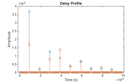
Plot the delay profile and path gains of a TGax channel.

Create an impulse.

input = zeros(100,4);
input(10) = 1;

Create the TGax channel System Object. Enable path gains at the output, and specify path loss, 20 MHz of channel bandwidth, a 4x2 MIMO channel, four penetrated floors, and a sampling rate of 1 GHz.

tgax = wlanTGaxChannel;
tgax.LargeScaleFadingEffect = 'Pathloss';
tgax.ChannelBandwidth = 'CBW20';
tgax.NumTransmitAntennas = 4;
tgax.NumReceiveAntennas = 2;
tgax.NumPenetratedFloors = 4;
tgax.RandomStream = 'mt19937ar with seed';
tgax.Seed = 10;
tgax.SampleRate = 1e9;
tgax.PathGainsOutputPort = true;

Filter the input impulse. Use the TGax channel object to generate the output response and the path gains.

[out,pathgains]= tgax(input);

Plot the output impulse response of the channel. The channel has two delay profiles, one per each receive antenna.

figure
time = (1/tgax.SampleRate)*(0:length(input)-1);
stem(time,abs(out))
xlabel('Time (s)')
ylabel('Amplitude')
title('Delay Profile')

Figure contains an axes object. The axes object with title Delay Profile, xlabel Time (s), ylabel Amplitude contains 2 objects of type stem.

The path gains of the channel are contained in a four dimensional array since the channel has nine resolvable paths, four transmit antennas and two receive antennas.

size(pathgains)
ans = 1×4

   100     9     4     2

Algorithms

expand all

The algorithms used to model the TGax channel are based on those used for the TGn channel (as described in wlanTGnChannel and TGn Channel Models [2]) and the TGac channel (as described in wlanTGacChannel and TGac Channel Model Addendum [3]). Complete information on the changes required to support TGax channels can be found in TGax Channel Model [1]. The changes to support the TGax channel include lower bandwidths, floor separation attenuation, wall separation attenuation, and path loss and shadowing.

References

[1] Jianhan, L., Ron, P. et al. TGax Channel Model. IEEE 802.11-14/0882r4, September 2014.

[2] Erceg, V., Schumacher, L., Kyritsi, P. et al. TGn Channel Models. Version 4. IEEE 802.11-03/940r4, May 2004.

[3] Breit, G., Sampath, H., Vermani, S. et al. TGac Channel Model Addendum. Version 12. IEEE 802.11-09/0308r12, March 2010.

[4] Kermoal, J. P., L. Schumacher, K. I. Pedersen, P. E. Mogensen, and F. Frederiksen. “A Stochastic MIMO Radio Channel Model with Experimental Validation.” IEEE Journal on Selected Areas in Communications. Vol. 20, No. 6, August 2002, pp. 1211–1226.

Extended Capabilities

Version History

Introduced in R2018a