Model-Based Design of Production Machines – Part 1: Import CAD models to Simulink
From the series: Model-Based Design of Production Machines
Overview
From food packaging to metal cutting and injection molding, leading industrial equipment and machinery OEMs use Model-Based Design with MATLAB® and Simulink® to address the increasing complexity of their products.
In the 1st part of this webinar series, you will learn how to create simulation models of your machines in Simulink by importing existing CAD files.
Highlights
Introduction to Unreal Engine API: The Simulink® 3D Animation™ toolbox provides functionality to build, visualize, and interact with virtual world and perform agent-based modeling by using the Unreal Engine® viewer.
About the Presenter
Jens Lerche is a senior application engineer focused on Industrial Systems Simulations. He specializes in mechatronic systems modeling, desktop simulation, automatic code generation and Model-Based Design with MATLAB® Simulink®, and Simscape. Jens has advanced experience in the design, development, and deployment of models for production equipment. He holds a M.Sc. in mechatronic engineering from the Technical University of Dresden, Germany.
Recorded: 12 Sep 2023
Hello, and welcome to the Model-Based Design of Production Machines webinar series. Today's webinar is the first of a four-part series, with one webinar taking place every two weeks. My name is Rares Curatu, and I'm an Industry Manager at MathWorks. Also with me is my colleague, Jens Lerche, from the Application Engineering Department, who will guide you through the technical part.
Thank you, Rares, for the introduction. As mentioned, my name is Jens Lerche, and I'm a senior application engineer at MathWorks here in Germany. For several years, I'm focused on machine builder and manufacturing equipment companies. And today, I will guide you through the technical part of our webinar. Back to you, Rares.
In this webinar series, we are delighted to share with you a Simulink example that explores the automation of a virtual assembly line. With our powerful tools, such as Simulink and the Robotic System Toolbox, we provide you with the ability to simulate and control various components within the assembly line environment. From robotic manipulators to conveyor belts and sensors, you will have the means to coordinate their movements and their interactions seamlessly.
Join us as we guide you through the process of designing and implementing advanced control algorithms that optimize your assembly lines' performance, enhancing efficiency and productivity. This immersive demonstration offers valuable insight into integrating robotics and automation, enabling you to address real-world assembly line challenges effectively. Thank you for joining us today and for your interest in using MATLAB and Simulink for streamlining the way that you are designing and developing manufacturing equipment. Now, let's get started.
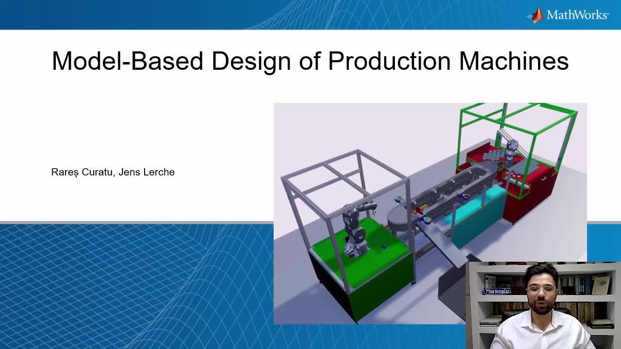
Here's a system overview of the example that we will be using throughout the webinar series. The model has five components that form the assembly line. The first robot is a Comau Racer V3. This robot picks up the cups and puts them in the shuttles. The second robot is a Mitsubishi RV-4F. The camera sensor in this robot's work cell detects the balls, and then this robot picks them up and places each one of them in a separate cup.
The shuttle track moves the shuttles from Robot 1, then to Robot 2, and then to the conveyor belt, before returning to Robot 1. The conveyor belt carries the cups away from the track and into a container. The remaining non-moving model parts comprise the static machine frame, which serves as the base for the assembly. It includes two work cells housing the robots, as well as the base for the central assembly.
During this webinar series, we will be starting with modeling and desktop simulation, and then move on to using hardware. These are typical steps developing machinery software using model-based design. After simulating the plant in a desktop environment, designing and simulating the controller, and visualizing the simulations, we will show you the steps you need to deploy the control algorithm to a Siemens PLC using Simulink PLC Coder.
This way, the control algorithm that you have been developing in Simulink will be equivalent to the code running on the PLC. To continue the validation and verification of the software on the PLC, we will deploy the simulation model of the plant to a real-time computer using Simulink Real-Time in a hardware-in-the-loop configuration. The real-time simulation will then communicate with a PLC over Profinet but also with the visualization of the plant over UDP.
On the screen now you see the agenda of the entire webinar series and how we plan to break up the content throughout the coming weeks. Today, in part 1, we will introduce you to the CAD model and show you how to import it into MATLAB to later use it in Simulink. In part 2, you will see how to design supervisory logic for your PLCs using Stateflow.
Part 3 is about how to bring this logic to any PLC. And then in part 4, we will round up the design process by testing the PLC in a hardware-in-the-loop simulation. During this presentation, if you have any questions, please feel free to enter them in the Q&A section. We will gladly answer them at the end of the presentation.
Now, without further ado, I would like to hand it over to Jens for the technical content. Thank you. Jens?
This is the agenda for part 1. It will be mainly about the creation of the model of the machine by using CAD files. And in the first step, I would like to give you a little bit of an introduction to different levels of physical details that can be modeled with MathWorks tools. In point 2, I will talk about the export of CAD files. In point 3, we will load these files and do some pre-processing. And after that, we will create the final Simulink model.
For the plant modeling of the system, we use the new Unreal Engine API that comes with Simulink 3D Animation. Unreal Engine by Epic Games is the environment that is used to create and simulate the scene. With our API, we support two workflows. First, directly create the virtual reality in the Unreal Editor, a tool provided by Epic Games. Second, use the API to import CAD models and a subset of functionality to create basic scenes with MATLAB code.
The benefits, in comparison to a multibody tool, are increase in modeling speed; second, an increase in simulation speed for an equal size model; third, implicit contact modeling. That means you don't have to define collisions during editing time. The downside is a loss of physical detail due to a simplified physics engine in Unreal.
Our suggestions. If you are about to design a mechanical system or you are about to better understand the dynamics of an existing one, we encourage you to use Simscape Multibody. In case you expect the mechanics to work properly under known boundary conditions and you are more interested in the automation process, how a large number of mechanical subsystems interact with each other, Simulink 3D Animation might be a better fit.
Here is an example for a multibody simulation. Krones has developed a package-handling robot called the Robobox. It is a fully automated system that efficiently groups packs of bottled beverages for palletization. The redesigned system, incorporating a tripod robot with a parallel kinematic design, can group packs into predefined layer patterns at the rate of 500 layers per hour.
Krones engineer used Simulink and Simscape Multibody to create a digital twin of the robot, allowing them to run simulations for design optimization, testing, and predictive maintenance. The digital twin has helped improve robot performance, shorten product development time, and significantly reduce testing time.
Now we are going to export the CAD files from SolidWorks using the FBX and the URDF file format. Here you can see the CAD model of our system. If you have a closer look, you see the robots are not included. And also, the shuttles are missing. And this makes sense, especially when you want to import static parts of the machines. So parts that are not moving. That gives you a lot of freedom.
And for these static parts, it's much easier because you don't have to define joints or something else. So we take this static part as a whole and export it. So we are choosing the name, static, or static components. In MATLAB, we can now see our created file.
And we want to load it to a new Unreal scene. Therefore, we use our API to define a world first, then create an actor, named static. This will be the actor defining our whole assembly we just exported. We will add this actor to the world and load a geometry to it and run it.
You can see this is our machine now. The panels are closed. They will have been invisible in our SolidWorks file, but that's no problem. We can check on properties. And for example, we can hide these as well. And then we can look right into our assembly line. Yes, of course. We now have some actions to change colors and so on. But I think that's it for now.
So we imported the static components, and now let's talk about the active or movable components. The robots are good examples. Let's have a more abstract look at them. The real robot, obviously, has solids and joins in between combined to an open kinematic chain. What we want is that if we later change the angle or the angular velocity of the base joint here, all other parts should move with it.
That is not self-evident. So the relations of joints and solids must be part of the file we will export. We have two options to define these relations. In our CAD model, we create a hierarchy, or a tree, for the robot, putting the base on top. And let the following parts be a sub part or a child of it. Then we will repeat that for the rest of the parts down to the tool.
Important here is to place the origin of each solid in the axis of the corresponding joint. Once we have done this in our CAD model, we can use the export to an FBX file format. The FBX format supports not just the export of solids and meshes-- so the geometries-- but also the hierarchy of the model.
The second way is to use a URDF format. URDF stands for Unified Robotics Description Format. It is an XML specification used in industry to model multibody systems, such as robotic manipulator arms for manufacturing assembly lines. While with the FBX format we worked with a hierarchy, with URDF, we work with definition of joints, or mates as it is called in SolidWorks. There is a free available URDF plugin for SolidWorks available at the internet.
There comes an additional benefit with the URDF. For later control of the robot, like calculation of trajectories and inverse kinematics, our Robotics System Toolbox works seamlessly with URDF files. I will show you this later in our Simulink model.
Let me now switch to SolidWorks, where I will show a hierarchy for an FBX export. As mentioned, in the Simulink model, we will work with the URDF format. In the interest of time, I won't go into a tutorial how to prepare your CAD model for a URDF export because there are good tutorials out there.
Here you can see one of our robots. This is the base and so on. We have now the hierarchy with all the following solids. And the export is actually the same as it is for the static components. Now, let's load the exported files into MATLAB and do some pre-processing to use it later in our scene.
Back in MATLAB, we can see the FBX file we exported, and I extended this little script from the pure aesthetic components of the machine to the robot. The robot becomes the child of the machine. I add some rough translation to position it in the scene. It's not 100% correctly, you will see later on, but that's the way it's done in principle.
And I also have a little box I create from a generic shape. So it's not CAD imported. Just to show you that it's also possible to use generic shapes to create actors in the scene. I then run the world. And finally, I save it as a MAT-file in static and robot. Let's do this.
So now we can see the box we created. This slide we could use later on. And behind this pedal, we see our robot, as I mentioned, roughly placed in here. Yes. And this is how to create a scene. We also see in our folder that this static and robot MAT-file got created.
So once we used our, let's call it, world creation script, we have now our MAT-file. We can call the scene in any other way. So like just having a script to call the scene again. And later on, we will show it in Simulink. We will also call the same MAT-file of the scene we just created.
For URDF, the workflow is actually the same. We have a complete folder with meshes. These are STL files. In this case, it could be textures as well. But this is empty for our model. And this is the actual URDF file. And what you can see here is it's already moving because I gave it a signal angular velocity for part four. And you can see it's spinning right around its joint here.
Now I would like to show you how to use the created scene in a Simulink model and starting to create inputs and outputs of the plant for later connecting it to an automation control logic. So we are back in MATLAB. And first, I would like to show you the library that comes with Simulink 3D Animation for the Unreal API.
It's not a lot of blocks, but it's really not needed. The basic components are the Simulink 3D Scene Configuration block and the Simulation 3D Actor that we will use. You also see a camera. So just for information, it is possible to place a camera anywhere in the scene. It's also possible to attach it to actors that are moving. So you can use this to create image processing algorithms, but this won't be part of this webinar series.
Opening a first little model, including our robot from our URDF import, should give you a overview. This is the Configuration block. We are using just the default scene with a sample time. There is also an option for weather. We are here focusing on indoor production equipment, but this could be very useful if you want to create autonomous harvesting equipment, for example. Outdoor application, let's say.
We don't have to do any changes in here for now. The most important block is the Simulation 3D Actor. In this block, we can define actors. And as you saw in the MATLAB script, you have to give an actor, of course, a name. And in this case, we call it robot. The parent actor is the scene itself. And we have a little script here to import our robot, load it, and make it look pretty and make all the parts movable.
We could create actors also from an external input, in case you want to create production goods. We will see this later on with the balls that come into the scene. We can also reference by name. So reference actors that already exist in the scene. And we call them by name to do certain manipulation to the actor. And of course, the same for the instance number of the actor.
There's some Transformation tab. Important here is the Input tab. So at the moment, we are choosing two inputs. We want to change angular velocity, in this case. And what you can see here clearly is the structure of the robot, the hierarchy. And here you have the properties you can select to a certain part. Let's go for part two. We can also change mass. Put it in here. But we won't do that. So take it out again.
OK. We can do the same for the outputs. And here, I'm not using outputs. We will see it later in the larger model. We can also activate events for collision, overlap, or click interaction with the scene. But this won't be part of this webinar.
Here are the inputs for the angular velocity of two joints. I attached some dashboards to it so we can do some manual manipulation. So you can see that we can change the values. And that's basically how to create a Simulink model that has an Unreal Engine API.
So now we are on the folder for the complete project of our assembly line we showed in the beginning. First, I want to point out the MAT-file that includes the complete scene. In this case, we have an additional file that calls this MAT-file, the scene, and adds some additional parts, like a little container to capture all the cups and balls that got produced.
We have a slide that leads to the container, what's a basic block. Create from a shape. And we have many lines that hide all the covers you saw on the CAD model. So we can look into the machine, what's going on there.
Looking at the Simulink model itself, basically you see the Scene Configuration blocks. You see the automation state machine. This will be part of the second part of the webinar series. Here you see all the actors. So the Unreal APIs for all the actors included in the scene. And in the middle, you see the robot's kinematic. I will go into this in more detail.
The Scene Configuration block, there's nothing set in here different than in the example I showed before. Here is the block for loading the complete scene, calling this M-file you just saw. So now all the actors are in the scene already. They are known. Except for the balls. The balls get created-- create a step from an external input that is coming from our state machine, in this case.
It's in there with some dimensions. Some color. Positioning. Make it movable. The shuttles as well. They have translation and rotation as an input, and we reference them by name. We know their names, of course. Shuttle 1 to shuttle 4. And we just address them by the names.
For the robot, the same. Reference by name. Much more inputs for all the joints. And the rest is some functionality to get things running, to do some reparenting during the simulation so that the balls, for example, stick to the tool, and the cups to the shuttle, and the balls to the shuttle later on, and so on. This is some functionality that's implemented in here.
Before, I mentioned the URDF format that fits well to our Robotics System Toolbox functionality. So this is actually what we do in here, is calling the URDF files, the Rigid Body Tree, and this is extracted from our URDF file we created. Yes. And that's basically the model itself. Let's run it.
That's it for the technical part of our webinar for today. Thank you for your interest, and I will hand over to Rares.
Thank you, Jens. I'm quite excited to see the level of enthusiasm and the level of interest that the industry is showing in these topics. This is the end of today's presentation. But before we end today's session, we will be answering your questions. So if you haven't done so already, please type your questions in the Q&A section.
Please don't forget to register and attend the next webinars. Taking place every two weeks, we will be guiding you through the steps of designing machinery software with model-based design. If you plan to attend Forum Industria Digitale in Italy, SPS in Germany, or the Precision Fair in the Netherlands in November, we would be happy to meet you there in person and talk about your projects.
In the meanwhile, if you want to take a look at what else industrial automation and machinery engineers are using MATLAB and Simulink for, please visit mathworks.com/industrial-automation-machinery. Thank you for your attention, and thank you for your interest. And now, let's take a look at the Q&A section.


Seleccione un país/idioma
Seleccione un país/idioma para obtener contenido traducido, si está disponible, y ver eventos y ofertas de productos y servicios locales. Según su ubicación geográfica, recomendamos que seleccione: United States.
También puede seleccionar uno de estos países/idiomas:
América
- América Latina (Español)
- Canada (English)
- United States (English)
Europa
- Belgium (English)
- Denmark (English)
- Deutschland (Deutsch)
- España (Español)
- Finland (English)
- France (Français)
- Ireland (English)
- Italia (Italiano)
- Luxembourg (English)
- Netherlands (English)
- Norway (English)
- Österreich (Deutsch)
- Portugal (English)
- Sweden (English)
- Switzerland
- United Kingdom (English)