EdgeFeed
R2026bDescription
Use the EdgeFeed object to specify the
FeedDefinitions property in a parent pcbStack
object.
The EdgeFeed object excites the structure from the edge of the PCB,
typically representing a microstrip or stripline launch.
Creation
Description
f1 = EdgeFeed creates a defaultEdgeFeed
object.
f1 = EdgeFeed( sets
object properties using one or more name-value arguments.
PropertyName=Value)PropertyName is the property name, and Value is
the corresponding value. You can specify several name-value arguments in any order as
PropertyName1=Value1,...,PropertyNameN=ValueN. Properties that you
do not specify retain their default values.
Properties
Examples
Define the patch, feed line, and board dimensions. The patch dimensions set the resonant frequency, in this case, near 2.4 GHz on a 1.6 mm FR4 substrate. Define the feed line width for a nominal 50 Ω line impedance. The feed line runs from the patch edge to the board edge. Apply the EdgeFeed here.
Lp = 0.0275;
Wp = 0.0375;
Wf = 0.0030;
Lb = 0.070;
Wb = 0.070;
sub = 1.6e-3;
Lf = Lb/2 - Lp/2;
Define an FR4 substrate and set its thickness.
d = dielectric("FR4");
d.Thickness = sub;
Create the patch and the feed line as rectangles using the antenna.Rectangle class, then combine them into a single conductor. Position the feed line so that it joins the patch at one edge and extends to the edge of the board.
patch = antenna.Rectangle(Length=Lp, Width=Wp, Center=[0 0]);
feedX = -(Lp/2 + Lf/2);
feedLine = antenna.Rectangle(Length=Lf, Width=Wf, Center=[feedX 0]);
top = patch + feedLine;
Define the ground plane as a full-board rectangle. Create the pcbStack object as a three-layer stack: the patch and feed line on top, the dielectric in the middle, and the ground plane on the bottom.
gnd = antenna.Rectangle(Length=Lb, Width=Wb);
p = pcbStack;
p.BoardShape = antenna.Rectangle(Length=Lb, Width=Wb);
p.BoardThickness = sub;
p.Layers = {top, d, gnd};
To enable the FeedDefinitions property, set the FeedFormat property to FeedDefinitions.
p.FeedFormat = 'FeedDefinitions';Create and orient the EdgeFeed object at the board edge where the feed line terminates. Use the SignalLocations property to place the feed at the outer end of the feed line. Set SignalWidths to match the feed line width. Reference the top conductor and the ground plane in the SignalLayers and GroundLayers properties respectively. The feed line must reach the board edge for the edge feed to attach to the conductor.
xEdge = -Lb/2;
f = EdgeFeed(SignalLocations=[xEdge 0], SignalWidths=Wf, ...
    SignalLayers=1, GroundLayers=3);
p.FeedDefinitions = f;
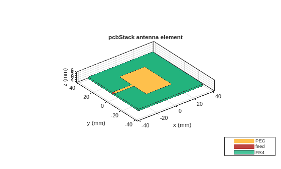
View the structure to confirm the patch, the feed line reaching the board edge, and the ground plane.
figure
show(p)
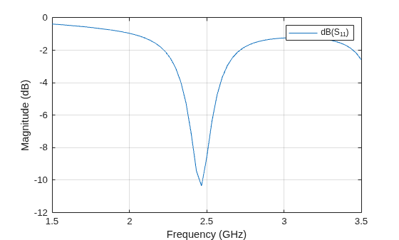
Compute and plot the reflection coefficient. The patch resonates near 2.47 GHz.
s = sparameters(p, linspace(1.5e9, 3.5e9, 61));
figure
rfplot(s)
Version History
Introduced in R2026b

