Configure AUTOSAR Adaptive Software Components
R2026bIn Simulink®, you can use the Property Inspector, Service Mappings Editor, and AUTOSAR Dictionary to configure AUTOSAR Adaptive software components and compositions. For more information about modeling AUTOSAR Adaptive software components and designing service interfaces, see Model AUTOSAR Adaptive Software Components.
Configure Simulink Model as AUTOSAR Adaptive Software Component
This example configures a Simulink representation of an automotive algorithm as an AUTOSAR Adaptive software component.
Open example model
LaneGuidance.
openExample("LaneGuidance");
In the Model Configuration Parameters dialog box, on the Code
Generation pane, configure the model for AUTOSAR Adaptive code
generation. Set System target file to
autosar_adaptive.tlc. Apply the change.
The target file selection affects these model settings:
Language is set to
C++.Language standard is set to
C++14 (ISO).Toolchain is set to
AUTOSAR Adaptive |
                        CMake
.

Note
To build a model with the AUTOSAR Adaptive | CMake
toolchain, you must specify the required libraries and include directories for your
AUTOSAR Adaptive stack in the Build process > Toolchain details section of the Code Generation pane.
Alternatively, you can change the toolchain to AUTOSAR Adaptive Linux
Executable to build without specifying these paths. For more
information, see Build Library or Executable from AUTOSAR Adaptive Model.
Configure the model as an AUTOSAR Adaptive software component with the AUTOSAR
Component Quick Start tool. From the Apps tab, open the AUTOSAR Component
Designer app. When you open the app for a model that is configured with the
autosar_adaptive.tlc system target file, but you have not mapped
to an AUTOSAR software component, the AUTOSAR Component Quick Start tool runs.
Advance through the steps of the AUTOSAR Component Quick Start tool. Each step prompts you for input to define your software component configuration. Click Finish. The model opens in the AUTOSAR software component perspective. The AUTOSAR software component perspective shows the software component boundary and its ports.

To view and configure service properties of software component ports and their
elements, open the Property Inspector. Select software component port
LeftSensor. The Property Inspector displays the service
properties for port element LeftSensor.LaneDistance. The port element
has execution service property Sample time is set to
-1 and these default communication service property
values:
| Communication Service Property | Value |
|---|---|
| Receiver service | Default: Queued |
| Queue capacity | Default: 16 |
| Initial value | 0 |
| Status element | <None> |
| Timeout | Default: Inf |

In the Property Inspector, select port element LaneDistance in the
bus hierarchy of software component port LeftSensor. Change the
service properties of this port element to these values:
| Queue capacity | 20 |
| Initial value | 3 |
| Timeout | 1.5 |

Configure AUTOSAR Software Component Port Interfaces and C++ Namespaces
To configure bus element ports for AUTOSAR code generation, set C++ namespaces in
the Architectural Data section of a linked Simulink data dictionary. The PortInterfaces data dictionary
linked to example model autosar_LaneGuidance already contains the
port interfaces used in the example. In this section, you link the dictionary, assign
interfaces to ports, and configure C++ namespaces.
Open example model
autosar_LaneGuidance.openExample("autosar_LaneGuidance");Link data dictionary
PortInterfaces.slddtoautosar_LaneGuidance. On the Modeling tab, select Design > Link to Data Dictionary.In the Model Properties dialog box, click the Browse button and select
PortInterfaces.sldd. Apply your changes.Return to the software component model and assign data interfaces to the appropriate ports by using the Interface Editor (System Composer). Open the AUTOSAR Component Designer app. From the AUTOSAR tab, select Interface Editor. The Interface Editor opens.
Expand the
PortInterfacesnode. Select theLeftSensorandRightSensorsoftware component ports. Then, right-click data interfaceSensorInterfacein the Interface Editor and click Assign to selected port(s). Similarly, assign data interfaceHazardInterfaceto theHazardIndicatorsoftware component port.
Next, configure C++ namespaces for each port interface by using the Architectural Data Editor.
Open the Architectural Data Editor by entering
archdataeditorin the MATLAB® Command Window. Then, open thePortInterfacesdata dictionary.On the Interfaces tab, select
SensorInterface. Expand the Code Generation section. Set C++ Namespace tocompany::chassis::perceptionand Header file toimpl_type_interfaces.h. SelectHazardInterface, and then set C++ Namespace tocompany::chassis::actuationand Header file toimpl_type_interfaces.h.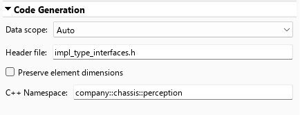
Save and close the data dictionary, and save the model.
Configure AUTOSAR Adaptive XML Options and Packages
In the AUTOSAR Dictionary, component elements appear in a tree format under the component that owns them. To access component elements and their properties, expand the component name.
Configure AUTOSAR Adaptive software component elements and properties:
Open example model
autosar_LaneGuidance, which was configured with a mapped AUTOSAR Adaptive software component in the previous sectionFrom the Apps tab, open the AUTOSAR Component Designer app.
Open the AUTOSAR Dictionary. On the AUTOSAR tab, click AUTOSAR Dictionary.
Expand the AdaptiveApplications node. The adaptive applications view in the AUTOSAR Dictionary displays adaptive software components. You can rename AUTOSAR Adaptive software components as they appear in the exported XML file, without changing the model name, by editing Name in this view.

Select the LaneGuidance node. The component view in the AUTOSAR Dictionary displays the name and type of the selected component, and component options for ARXML file export.

Specify the AUTOSAR package path for the component by setting Package to
/CompanyName/Powertrain. Alternatively, edit AUTOSAR package paths by using the AUTOSAR Package Browser. For more information about the AUTOSAR Package Browser, see Configure AUTOSAR Packages.
For more information about configuring AUTOSAR Adaptive Service Interfaces in the AUTOSAR Dictionary, see Configure AUTOSAR Adaptive Service Interface Properties.
Build and Generate Code for AUTOSAR Adaptive Software Components
Build the AUTOSAR Adaptive software component model. In the model window, press Ctrl+B.
This example explores the generated code and build artifacts for example model
autosar_LaneGuidance. Open model
autosar_LaneGuidance.
openExample("autosar_LaneGuidance");When you generate code for example model autosar_LaneGuidance, the
software generates these files:
autosar_LaneGuidance.cppandautosar_LaneGuidance.h— Simulink model algorithm code.autosar_LaneGuidance_comm.cpp— Service implementation code that calls intoara::comentities and APIs representing the model's communication elements.main.cpp— Completemain()function that aggregates entry point scheduling data and calls the scheduler with this information.autosar_LaneGuidance.arxml— AUTOSAR XML (ARXML) description of the adaptive software component, including service interface definitions with namespaces and events.autosar_LaneGuidance_ExecutionManifest.arxmlandautosar_LaneGuidance_ServiceInstanceManifest.arxml— ARXML manifest files for application service interface and deployment configurations.ServiceInstanceManifest.json,ExecutionManifest.json, andvsomeip.json— JSON manifest files that provide descriptions of software application behavior at run time, including queue capacity and timeout values for each port element.AUTOSAR Runtime for Adaptive Applications (ARA) service header files under the
services/aragen/folder, organized by the C++ namespaces configured in the data dictionary.CMakeLists.txtfiles for building the library and executable with CMake.
The generated service implementation code contains the C++ namespaces you configured
in the data dictionary to instantiate ARA proxy and skeleton objects. For example,
required port LeftSensor uses the
company::chassis::perception namespace.
/* Include service (proxy/skeleton) class headers */
#include "company/chassis/perception/sensorinterface_proxy.h"
#include "company/chassis/actuation/hazardinterface_skeleton.h"

std::unique_ptr<company::chassis::perception::proxy::SensorInterfaceProxy>
    LeftSensor;
std::unique_ptr<company::chassis::perception::proxy::SensorInterfaceProxy>
    RightSensor;

std::unique_ptr<company::chassis::actuation::skeleton::HazardInterfaceSkeleton>
    HazardIndicator;
The service initialization code subscribes to events on the required ports and offers the provided services to the execution environment.
  // Subscribe to events on the LeftSensor required port
  tmp_LeftSensor->TurnIndicator.Subscribe(
      manifest->GetQueueCapacity("LeftSensor", "TurnIndicator"));
  tmp_LeftSensor->LaneDistance.Subscribe(
      manifest->GetQueueCapacity("LeftSensor", "LaneDistance"));
  tmp_LeftSensor->CarInBlindSpot.Subscribe(
      manifest->GetQueueCapacity("LeftSensor", "CarInBlindSpot"));

  // Offer service on the HazardIndicator provided port
  tmp_HazardIndicator->OfferService();
The generated main() function (main.cpp)
provides a complete implementation of entry point functions for the deployed AUTOSAR
Adaptive software application.
/* Task wrapper function definitions */
void autosar_LaneGuidance_Task1(void) { autosar_LaneGuidance_step(); }

/* Model descriptor */
ec::scheduler::ModelInfo autosar_LaneGuidance_Info = {
    "autosar_LaneGuidance",
    autosar_LaneGuidance_initialize,
    autosar_LaneGuidance_terminate,
    ...
    {task_1},
    ...
    1.000000e-01};

int main(int argc, char *argv[]) {
  return ec::scheduler::runModel(argc, argv, autosar_LaneGuidance_Info);
}
The generated ServiceInstanceManifest.json file captures the queue
capacity and timeout values you configured for each port element. The generated C++
service implementation code reads these values from the JSON manifest at run time. For
example, the JSON manifest for software component port LeftSensor
specifies the service properties for each data
element:
...
  "RequiredPorts": [
    {
      "Name": "LeftSensor",
      "InstanceSpecifier": "LaneGuidance/LaneGuidance_RootSwComponentPrototype/LeftSensor",
      "InstanceID": "42885",
      "CommunicationMiddleware": "SOMEIP",
      "ServiceID": "42885",
      "MajorVersion": 0,
      "MinorVersion": 4294967295,
      "SOMEIP_EventGroupID": 42885,
      "Data": [
        {
          "Name": "LaneDistance",
          "SOMEIP_EventID": 33035,
          "QOS": {
            "QueueCapacity": 20,
            "AliveTimeout": "1.5"
          }
        },
        {
          "Name": "TurnIndicator",
          "SOMEIP_EventID": 40966,
          "QOS": {
            "QueueCapacity": 16,
            "AliveTimeout": "INF"
          }
        },
        {
          "Name": "CarInBlindSpot",
          "SOMEIP_EventID": 57468,
          "QOS": {
            "QueueCapacity": 16,
            "AliveTimeout": "INF"
          }
        }
      ],...
The generated service implementation code in
autosar_LaneGuidance_comm.cpp reads the queue capacity from the
JSON manifest when subscribing to events, and uses the timeout value to implement alive
timeout logic:
...
// Variables for reading incoming event data
double var_LeftSensor_LaneDistance{3.0};
double var_LeftSensor_TurnIndicator{0.0};
double var_LeftSensor_CarInBlindSpot{0.0};
double var_RightSensor_LaneDistance{0.0};
double var_RightSensor_TurnIndicator{0.0};
double var_RightSensor_CarInBlindSpot{0.0};
...
get_LeftSensor_LaneDistance(double *LeftSensor_LaneDistance_value) {
...
  *LeftSensor_LaneDistance_value = var_LeftSensor_LaneDistance;
  auto current_timestamp = std::chrono::steady_clock::now();
  if (status == SlSignalStatus::COM_NOT_AVAILABLE) {

    return status;
  }

  auto elapsed_time = std::chrono::duration<double>(
      current_timestamp - last_received_tp_LeftSensor_LaneDistance);
  if (elapsed_time > time_out_duration_LeftSensor_LaneDistance) {

    status = SlSignalStatus::TIMEOUT;
  }

  if (sampleRead) {

    last_received_tp_LeftSensor_LaneDistance = current_timestamp;
  }

  return status;
}
...
The exported ARXML files describe the AUTOSAR Adaptive Service Interfaces with the
namespaces you configured, the package path you set for the component, and the
communication properties you set for software component ports and elements. For example,
the SERVICE-INTERFACE for port interface
SensorInterface uses namespace
company::chassis::perception:
<SERVICE-INTERFACE>
    <SHORT-NAME>SensorInterface</SHORT-NAME>
    <NAMESPACES>
        <SYMBOL-PROPS>
            <SHORT-NAME>company</SHORT-NAME>
            <SYMBOL>company</SYMBOL>
        </SYMBOL-PROPS>
        <SYMBOL-PROPS>
            <SHORT-NAME>chassis</SHORT-NAME>
            <SYMBOL>chassis</SYMBOL>
        </SYMBOL-PROPS>
        <SYMBOL-PROPS>
            <SHORT-NAME>perception</SHORT-NAME>
            <SYMBOL>perception</SYMBOL>
        </SYMBOL-PROPS>
    </NAMESPACES>
    <EVENTS>
        <VARIABLE-DATA-PROTOTYPE>
            <SHORT-NAME>LaneDistance</SHORT-NAME>
            ...
        </VARIABLE-DATA-PROTOTYPE>
        <VARIABLE-DATA-PROTOTYPE>
            <SHORT-NAME>CarInBlindSpot</SHORT-NAME>
            ...
        </VARIABLE-DATA-PROTOTYPE>
    </EVENTS>
</SERVICE-INTERFACE>
For more information about configuring code generation for AUTOSAR Adaptive software components, see Configure AUTOSAR Adaptive Code Generation.
For more information about deploying AUTOSAR Adaptive software applications, see Build Library or Executable from AUTOSAR Adaptive Model and Build Out of the Box Linux Executable from AUTOSAR Adaptive Model.
See Also
Topics
- Model AUTOSAR Adaptive Software Components
- Create AUTOSAR Software Component in Simulink
- Configure AUTOSAR Adaptive Service Interface Properties
- Model AUTOSAR Adaptive Service Communication and Execution Behavior
- Configure AUTOSAR Adaptive Code Generation
- Comparison of AUTOSAR Classic and Adaptive Platforms

