ofdmPilotConfig
Description
The ofdmPilotConfig object specifies the pilot location and pilot
symbol configuration for OFDM systems. Use this object to construct pilot symbol patterns
for user-defined OFDM systems and provide pilot symbol information to the
ofdmChannelEstimate function.
Creation
Syntax
Description
pilotcfg = ofdmPilotConfigofdmPiltoConfig object that specifies the pilot locations and
the pilot symbol configuration for a MIMO-OFDM system.
pilotcfg = ofdmPilotConfig(Name=Value)FFTLength=64 sets the total number of subcarriers to
64.
pilotcfg = ofdmPilotConfig(fftlen,numGuardBandCarriers,numSym,numTxStreams)
FFTLength property to the
fftleninput value.NumGuardBandCarriers property to the
numGuardBandCarriersinput value.NumSymbols property to the
numSyminput value.NumTransmitStreams property to the
numTxStreamsinput value.
The syntax also sets the StreamGroups, PilotLocations, and PilotSymbols property using the given input values. For this syntax, the number of transmit streams must be a nonnegative integer power of 2. For more information, see Computing Pilot Cluster Locations from FFT Length and Transmit Streams and Choosing Pilot Symbols for Pilot Locations.
Properties
Object Functions
Examples
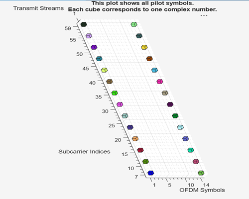
Specify an OFDM pilot configuration using default values.
pilotcfg = ofdmPilotConfig
pilotcfg =

  ofdmPilotConfig with properties:

               FFTLength: 64
    NumGuardBandCarriers: [2×1 double]
              NumSymbols: 14
      NumTransmitStreams: 1
            StreamGroups: {[1]}
          PilotLocations: {[1×2×28 double]}
            PilotSymbols: {[1×1×28 double]}
Plot the configuration.
plot(pilotcfg)
Create an OFDM system with 64-subcarriers and two transmit streams.
fftlen = 64;                % FFT length (number of subcarriers)
numGuardCarriers = [6; 5];  % Number of guard band carriers (lower; upper)
numSym = 14;                % Number of OFDM symbols
numTxStreams = 2;    % Number of transmit streams
pilotcfg = ofdmPilotConfig(fftlen,numGuardCarriers,numSym,numTxStreams)
pilotcfg =

  ofdmPilotConfig with properties:

               FFTLength: 64
    NumGuardBandCarriers: [2×1 double]
              NumSymbols: 14
      NumTransmitStreams: 2
            StreamGroups: {[1 2]}
          PilotLocations: {[2×2×52 double]}
            PilotSymbols: {[2×2×52 double]}
StreamGroups: {[1 2]}value shows that both streams are grouped together. At each pilot location, both streams transmit pilot symbols at the same time and frequency, but with different orthogonal values.PilotLocations: {[2-by-2-by-52 double]}is a 3-D array showing the placement of pilot symbols. First dimension is the number pilot locations per cluster. Each location is a [subcarrier;symbol} pair. Second dimension is always 2 representing a two-element coordinate where one coordinate is the subcarrier index and the other coordinate is OFDM the symbol index. Third dimension is the number of clusters.PilotSymbols: 2-by-2-by-52 doubleis a 3-D array of the actual pilot values. First dimension is the number of pilot symbols per cluster. Second dimension is the number of streams per group. Third dimension is the number of clusters. Each cluster has a 2-by-2 matrix of complex pilot values. Each column corresponds to a stream, and each row to a pilot in the cluster. These are chosen so that, in each cluster, the pilots sent by the two streams are orthogonal.
Plot the pilot symbol locations.
plot(pilotcfg)
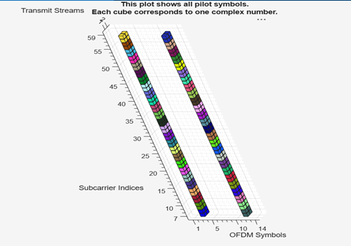
This 3-D plot shows the placement of pilot symbols for the MIMO-OFDM system.
Subcarrier Indices: Represents the frequency bins (subcarriers) used in the MIMO-OFDM system. Each tick is a subcarrier index.
OFDM Symbols: Represents the time dimension where each tick is an OFDM symbol index from 1 to 14.
Transmit Streams: Represents the transmit stream (or antenna). There are two streams, labeled 1 and 2.
Each colored cube represents a single pilot symbol, a known complex value transmitted at a specific subcarrier (frequency), OFDM symbol (time), and transmit stream (spatial layer).
Each color corresponds to a cluster of pilots. All cubes of the same color belong to the same cluster, which means they are used together for channel estimation at the receiver.
The cubes are arranged in a regular, repeating pattern across subcarriers and OFDM symbols. For each transmit stream (1 and 2), the cubes are stacked at the same (subcarrier, symbol) positions, but at different heights (streams).
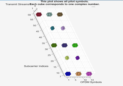
Create the pilot configuration object.
pilotcfg = ofdmPilotConfig( ...
    FFTLength = 64, ...
    NumGuardBandCarriers = [6;5], ...
    NumSymbols = 14, ...
    NumTransmitStreams = 4, ...
    StreamGroups={[1 2],[3 4]} );
Create pilot locations for each stream group.
pilotLocations1 = ofdmPilotGrid([1 2], [1 2], [7 31 57], [1 7 13]); % 2x2 (4) pilots each for 9 clusters
pilotLocations2 = ofdmPilotGrid([1 2], 1, [19 44], [4 10]);         % 2x1 (2) pilots each for 4 clusters
Check the number of clusters for each group.
numClusters1 = size(pilotLocations1, 3);
numClusters2 = size(pilotLocations2, 3);
Create pilot symbols for each group. The number of pilot symbols must match number of clusters).
pilotSymbols1 = randn(size(pilotLocations1,1), numel(pilotcfg.StreamGroups{1}), numClusters1);
pilotSymbols2 = randn(size(pilotLocations2,1), numel(pilotcfg.StreamGroups{2}), numClusters2);
Assign to the configuration object.
pilotcfg.PilotLocations = {pilotLocations1, pilotLocations2};
pilotcfg.PilotSymbols   = {pilotSymbols1, pilotSymbols2};
Validate and plot the configuration.
validate(pilotcfg)
plot(pilotcfg);
Algorithms
References
[1] Van de Beek, J.-J., O. Edfors, M. Sandell, S. K. Wilson, and P. O. Borjesson. “On Channel Estimation in OFDM Systems." Vehicular Technology Conference, IEEE 45th, Volume 2, IEEE, 1995.
Extended Capabilities
Version History
Introduced in R2026a