Maximum Loop Gain Goal
Purpose
Suppress gain of feedback loops at high frequency when using Control System Tuner.
Description
Maximum Loop Gain Goal enforces a maximum loop gain in a particular frequency band. This tuning goal is useful, for example, for increasing system robustness to unmodeled dynamics.
Maximum Loop Gain Goal imposes a maximum gain on the open-loop frequency response (L) at a specified location in your control system. You specify the maximum open-loop gain as a function of frequency (a maximum gain profile). For MIMO feedback loops, the specified gain profile is interpreted as an upper bound on the largest singular value of L.
When you tune a control system, the maximum gain profile is converted to a maximum gain constraint on the complementary sensitivity function, T = L/(I + L).
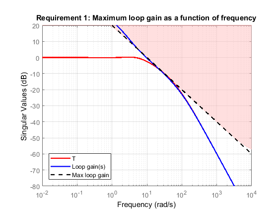
The following figure shows a typical specified maximum gain profile (dashed line) and a resulting tuned loop gain, L (blue line). The shaded region represents gain profile values that are forbidden by this requirement. The figure shows that when L is much smaller than 1, imposing a maximum gain on T is a good proxy for a maximum open-loop gain.
Maximum Loop Gain Goal is a constraint on the open-loop gain of the specified control loop. Thus, the loop gain is computed with the loop open at the specified location. To compute the gain with loop openings at other points in the control system, use the Compute response with the following loops open option in the Open-Loop Response Selection section of the dialog box.
Maximum Loop Gain Goal and Minimum Loop Gain Goal specify only high-gain or low-gain constraints in certain frequency bands. When you use these requirements, the software determines the best loop shape near crossover. When the loop shape near crossover is simple or well understood (such as integral action), you can use Loop Shape Goal to specify that target loop shape.
Creation
In the Tuning tab of Control System Tuner, select New Goal > Maximum gain for open-loop response to create a Maximum Gain Goal.
Command-Line Equivalent
When tuning control systems at the command line, use TuningGoal.MaxLoopGain to specify a maximum loop gain goal.
Open-Loop Response Selection
Use this section of the dialog box to specify the signal locations at which to compute the open-loop gain. You can also specify additional loop-opening locations for evaluating the tuning goal.
Shape open-loop response at the following locations
Select one or more signal locations in your model at which to compute and constrain the open-loop gain. To constrain a SISO response, select a single-valued location. For example, to constrain the open-loop gain at a location named
'y', click Add signal to list and select
 'y'. To constrain a MIMO response, select multiple signals or a vector-valued signal.Compute response with the following loops open
Select one or more signal locations in your model at which to open a feedback loop for the purpose of evaluating this tuning goal. The tuning goal is evaluated against the open-loop configuration created by opening feedback loops at the locations you identify. For example, to evaluate the tuning goal with an opening at a location named
'x', click
Add signal to list and select 'x'.
Tip
To highlight any selected signal in the Simulink® model, click ![]() . To remove a signal from the input or output list, click
. To remove a signal from the input or output list, click ![]() . When you have selected multiple signals, you can reorder
them using
. When you have selected multiple signals, you can reorder
them using ![]() and
and ![]() . For more information on how to specify signal locations
for a tuning goal, see
Specify Goals for Interactive Tuning.
. For more information on how to specify signal locations
for a tuning goal, see
Specify Goals for Interactive Tuning.
Desired Loop Gain
Use this section of the dialog box to specify the target maximum loop gain.
Pure integrator K/s
Check to specify a pure integrator shape for the target maximum loop gain. The software chooses the integrator constant, K, based on the values you specify for a target maximum gain and frequency. For example, to specify an integral gain profile with crossover frequency 10 rad/s, enter 1 in the Choose K to keep gain below text box. Then, enter 10 in the at the frequency text box. The software chooses the integrator constant such that the maximum loop gain is 1 at 10 rad/s.
Other gain profile
Check to specify the maximum gain profile as a function of frequency. Enter a SISO numeric LTI model whose magnitude represents the desired gain profile. For example, you can specify a smooth transfer function (
tf,zpk, orssmodel). Alternatively, you can sketch a piecewise target loop gain using anfrdmodel. When you do so, the software automatically maps the profile to a smooth transfer function that approximates the desired maximum loop gain. For example, to specify maximum gain of 100 (40 dB) below 0.1 rad/s, rolling off at a rate of –20 dB/dec at higher frequencies, enterfrd([100 100 10],[0 1e-1 1]).If you are tuning in discrete time, you can specify the maximum gain profile as a discrete-time model with the same sampling time as you use for tuning. If you specify the gain profile in continuous time, the tuning software discretizes it. Specifying the profile in discrete time gives you more control over the profile near the Nyquist frequency.
Options
Use this section of the dialog box to specify additional characteristics of the maximum loop gain goal.
Enforce goal in frequency range
Limit the enforcement of the tuning goal to a particular frequency band. Specify the frequency band as a row vector of the form
[min,max], expressed in frequency units of your model. For example, to create a tuning goal that applies only between 1 and 100 rad/s, enter[1,100]. By default, the tuning goal applies at all frequencies for continuous time, and up to the Nyquist frequency for discrete time.Stabilize closed loop system
By default, the tuning goal imposes a stability requirement on the closed-loop transfer function from the specified inputs to outputs, in addition to the gain constraint. If stability is not required or cannot be achieved, select
Noto remove the stability requirement. For example, if the gain constraint applies to an unstable open-loop transfer function, selectNo.Equalize loop interactions
For multi-loop or MIMO loop gain constraints, the feedback channels are automatically rescaled to equalize the off-diagonal (loop interaction) terms in the open-loop transfer function. Select
Offto disable such scaling and shape the unscaled open-loop response.Apply goal to
Use this option when tuning multiple models at once, such as an array of models obtained by linearizing a Simulink model at different operating points or block-parameter values. By default, active tuning goals are enforced for all models. To enforce a tuning requirement for a subset of models in an array, select Only Models. Then, enter the array indices of the models for which the goal is enforced. For example, suppose you want to apply the tuning goal to the second, third, and fourth models in a model array. To restrict enforcement of the requirement, enter
2:4in the Only Models text box.For more information about tuning for multiple models, see Robust Tuning Approaches (Robust Control Toolbox).
Algorithms
Evaluating Tuning Goals
When you tune a control system, the software converts each tuning goal into a normalized scalar value f(x). Here, x is the vector of free (tunable) parameters in the control system. The software then adjusts the parameter values to minimize f(x) or to drive f(x) below 1 if the tuning goal is a hard constraint.
For Maximum Loop Gain Goal, f(x) is given by:
Here, D is a diagonal scaling (for MIMO loops).
T is the complementary sensitivity function at the specified
location. WT is a frequency-weighting function
derived from the maximum loop gain profile you specify. The gain of this function roughly
matches the inverse of the specified loop gain for values ranging from –60 dB to 20 dB.
For numerical reasons, the weighting function levels off outside this range, unless the
specified gain profile changes slope outside this range. This adjustment is called
regularization. Because poles of
WT close to s = 0 or
s = Inf might lead to poor numeric conditioning
for tuning, it is not recommended to specify gain profiles with very low-frequency or very
high-frequency dynamics. For more information about regularization and its effects, see
Visualize Tuning Goals.
Although T is a closed-loop transfer function, driving f(x) < 1 is equivalent to enforcing an upper bound on the open-loop transfer, L, in a frequency band where the gain of L is less than one. To see why, note that T = L/(I + L). For SISO loops, when |L| << 1, |T| ≈ |L|. Therefore, enforcing the open-loop maximum gain requirement, |L| < 1/|WT|, is roughly equivalent to enforcing |WTT| < 1. For MIMO loops, similar reasoning applies, with ||T|| ≈ σmax(L), where σmax is the largest singular value.
Implicit Constraints
This tuning goal imposes an implicit stability constraint on the closed-loop sensitivity function measured at the specified, evaluated with loops opened at the specified loop-opening locations. The dynamics affected by this implicit constraint are the stabilized dynamics for this tuning goal. The Minimum decay rate and Maximum natural frequency tuning options control the lower and upper bounds on these implicitly constrained dynamics. If the optimization fails to meet the default bounds, or if the default bounds conflict with other requirements, on the Tuning tab, use Tuning Options to change the defaults.