Automated Parking Valet in Simulink
This example shows how to construct an automated parking valet system in Simulink® with Automated Driving Toolbox™. It closely follows the Automated Parking Valet MATLAB® example.
Introduction
Automatically parking a car that is left in front of a parking lot is a challenging problem. The vehicle's automated systems are expected to take over and steer the vehicle to an available parking spot. This example focuses on planning a feasible path through the environment, generating a trajectory from this path, and using a feasible controller to execute the trajectory. Map creation and dynamic obstacle avoidance are excluded from this example.
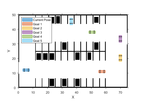
Before simulation, the helperSLCreateCostmap function is called within the PreLoadFcn callback function of the model. For details on using callback functions, see Model Callbacks (Simulink). The helperSLCreateCostmap function creates a static map of the parking lot that contains information about stationary obstacles, road markings, and parked cars. The map is represented as a vehicleCostmap
To use the vehicleCostmaphelperSLCreateUtilityStruct function converts the vehicleCostmap

The global route plan is described as a sequence of lane segments to traverse to reach a parking spot. Before simulation, the PreLoadFcn callback function of the model loads a route plan, which is stored as a table. The table specifies the start and end poses of the segment, as well as properties of the segment, such as the speed limit.
routePlan =

  5×3 table

       StartPose              EndPose           Attributes
    ________________    ____________________    __________

     4     12      0      56      11       0    1×1 struct
    56     11      0      70      19      90    1×1 struct
    70     19     90      70      32      90    1×1 struct
    70     32     90      52      38     180    1×1 struct
    53     38    180    36.3      44      90    1×1 struct
The inputs and outputs of many blocks in this example are Simulink buses (Simulink.Bus (Simulink)PreLoadFcn callback function of the model, the helperSLCreateUtilityBus function creates these buses.

Planning is a hierarchical process, with each successive layer responsible for a more fine-grained task. The behavior layer [1] sits at the top of this stack. The Behavior Planner block triggers a sequence of navigation tasks based on the global route plan by providing an intermediate goal and configuration for the Motion Planning and Trajectory Generation blocks. Each path segment is navigated using these steps:
Motion Planning: Plan a feasible path through the environment map using the optimal rapidly exploring random tree (RRT*) algorithm (
pathPlannerRRTTrajectory Generation: Smooth the reference path by fitting splines [2] to it using the Path Smoother Spline block. Then convert the smoothed path into a trajectory by generating a speed profile using the Velocity Profiler block.
Vehicle Control: The
HelperPathAnalyzerprovides the reference signal for the Vehicle Controller subsystem that controls the steering and the velocity of the vehicle.Goal Checking: Check if the vehicle has reached the final pose of the segment using
helperGoalChecker.
Explore the Subsystems
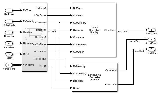
The Vehicle Controller subsystem contains a Lateral Controller Stanley block and a Longitudinal Controller Stanley block to regulate the pose and the velocity of the vehicle, respectively. To handle realistic vehicle dynamics [3], the Vehicle model parameter in the Lateral Controller Stanley block is set to Dynamic bicycle model. With this configuration, additional inputs, such as the path curvature, the current yaw rate of the vehicle, and the current steering angle are required to compute the steering command. The Longitudinal Controller Stanley block uses a switching Proportional-Integral controller to calculate the acceleration and the deceleration commands that actuate the brake and throttle in the vehicle.
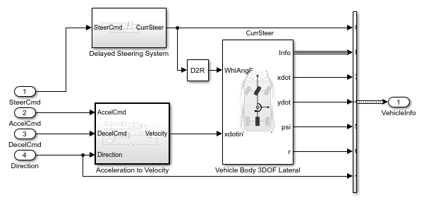
To demonstrate the performance, the vehicle controller is applied to the Vehicle Model block, which contains a simplified steering system [3] that is modeled as a first-order system and a Vehicle Body 3DOF (Vehicle Dynamics Blockset) block shared between Automated Driving Toolbox™ and Vehicle Dynamics Blockset™. Compared with the kinematic bicycle model used in the Automated Parking Valet MATLAB® example, this Vehicle Model block is more accurate because it considers the inertial effects, such as tire slip and steering servo actuation.
Simulation Results
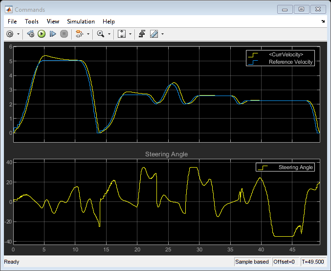
The Visualization block shows how the vehicle tracks the reference path. It also displays vehicle speed and steering command in a scope. The following images are the simulation results for this example:
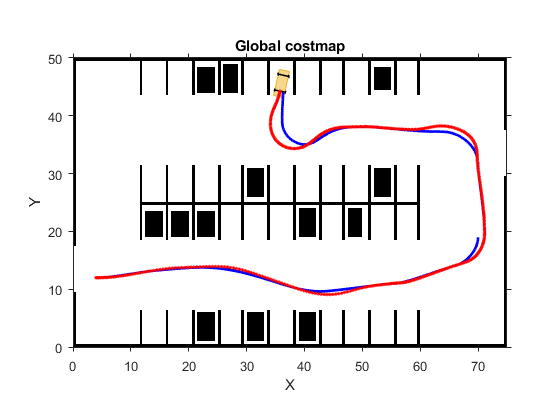
Simulation stops at about 45 seconds, which is when the vehicle reaches the destination.
Conclusions
This example shows how to implement an automated parking valet in Simulink.
References
[1] Buehler, Martin, Karl Iagnemma, and Sanjiv Singh. The DARPA Urban Challenge: Autonomous Vehicles in City Traffic (1st ed.). Springer Publishing Company, Incorporated, 2009.
[2] Lepetic, Marko, Gregor Klancar, Igor Skrjanc, Drago Matko, and Bostjan Potocnik, "Time Optimal Path Planning Considering Acceleration Limits." Robotics and Autonomous Systems, Volume 45, Issues 3-4, 2003, pp. 199-210.
[3] Hoffmann, Gabriel M., Claire J. Tomlin, Michael Montemerlo, and Sebastian Thrun. "Autonomous Automobile Trajectory Tracking for Off-Road Driving: Controller Design, Experimental Validation and Racing." American Control Conference, 2007, pp. 2296-2301.
See Also
Blocks
- Vehicle Body 3DOF (Vehicle Dynamics Blockset) | Lateral Controller Stanley | Path Smoother Spline | Longitudinal Controller Stanley | Velocity Profiler