Parameter Tuning and Signal Monitoring Using External Mode
You can use external mode simulations for rapid prototyping. An external mode simulation establishes a communication channel between Simulink® on your development computer and the target hardware that runs the executable file created by the code generation and build process.
Through the communication channel, you can:
Modify or tune block parameters in real time. When you change parameters in your model, Simulink downloads the new values to the executing target application.
Monitor and save signal data from the executing target application.
The low-level transport layer of the channel handles the transmission of messages. Simulink and the generated model code are independent of this layer. The transport layer and its interface code are isolated in separate modules that format, transmit, and receive messages and data packets.
Example: The Mandelbrot Set
To demonstrate how to run a model in external mode, create a model that uses the Mandelbrot set algorithm, configure the model for external mode simulation, and run the external mode simulation using an XCP on TCP/IP communication channel.
The Mandelbrot set is the region in the complex plane consisting of the values z0 for which the trajectories defined by this equation remain bounded at k→∞.
This figure shows the geometry of the Mandelbrot set. This view does not have the resolution to show the detailed structure of the fringe just outside the boundary of the set. At increasing magnifications, the Mandelbrot set exhibits an elaborate boundary that reveals progressively finer recursive detail. In this example, you calculate the Mandelbrot set in a region of interest.
Examine the Mandelbrot Set Algorithm
This example uses a function named mandelbrot_count that implements
the Mandelbrot set using MATLAB® commands that run on the CPU. The function vectorizes the calculation so
that every location updates simultaneously.
function count = mandelbrot_count(maxIterations, xGrid, yGrid)
% mandelbrot computation

z0 = complex(xGrid,yGrid);
count = ones(size(z0));

% Map computation to GPU
coder.gpu.kernelfun;

z = z0;
for n = 0:maxIterations
    z = z.*z + z0;
    inside = abs(z)<=2;
    count = count + inside;
end
count = log(count);
Create two variables xlim and ylim that specify
a highly zoomed part of the Mandelbrot set in the valley between the main cardioid and the
p/q bulb to its left. Create a 1000-by-1000 grid of real parts
(x) and imaginary parts (y) between these two
limits. Specify an iteration size of 500 to render the image in full
resolution.
maxIterations = 500;
gridSize = 1000;
xlim = [-0.748766713922161,-0.748766707771757];
ylim = [0.123640844894862,0.123640851045266];

x = linspace(xlim(1),xlim(2),gridSize);
y = linspace(ylim(1),ylim(2),gridSize);
[xGrid,yGrid] = meshgrid(x,y);
Call the function mandelbrot_count to calculate the Mandelbrot set
over each grid location.
count = mandelbrot_count(maxIterations,xGrid,yGrid);
Create Mandelbrot Model
Create a Simulink model and insert a MATLAB Function block from the User-Defined Functions library.
Double-click the MATLAB Function block.
Replace the default function signature with the code of the
mandelbrot_countfunction. The function header declaresmaxIterations,xGrid, andyGridas input arguments, withcountas the return value.In the top model, right-click the MATLAB Function block and click Block Parameters (Subsystem). On the Code Generation tab, set Function packaging to
Reusable function.If the Function packaging parameter is set to another value, CUDA® kernels may not get generated.
Add two Inport (Simulink) blocks and one Outport (Simulink) block.
Add a Constant (Simulink) block to represent the
maxIterationsinput. Double-click the block and set the Constant value parameter to 500.Connect these blocks as shown in the diagram. Save the model as
mandelbrot_top.slx.
Configure the Model
Configure the model for external mode simulation on an NVIDIA® Jetson™ board.
In the Apps tab on the Simulink toolstrip, in the Setup to Run on Hardware section, click Run on Hardware Board.
In the Run on Hardware Board window, set Hardware Board to
NVIDIA Jetson. Setting up the model for Jetson automatically sets the solver Type parameter toFixed-step.To make the model run until the target application receives a stop message from Simulink, make the stop time infinite. On the Hardware tab, set Stop time to
inf.Click Hardware Settings.
On the Code Generation > Optimization pane, set the Default parameter behavior parameter to
Tunable.Click OK.
Alternatively, you can configure the model programmatically by using the set_param (Simulink) function.
set_param("mandelbrot_top","HardwareBoard","NVIDIA Jetson");
set_param("mandelbrot_top","StopTime","inf");
set_param("mandelbrot_top","DefaultParameterBehavior","Tunable");
Configure Signal Logging
The methods you can use to log signals depends on the communication interface Simulink uses to run the application in external mode. The MATLAB Coder™ Support Package for NVIDIA Jetson and NVIDIA DRIVE® Platforms supports these communication interfaces:
| Communication Interface | Description |
|---|---|
| TCP/IP | To monitor signals in external mode simulations over TCP/IP, use blocks from the Sinks (Simulink) library to log and visualize data. |
| XCP on TCP/IP | In external mode simulations using the Universal Measurement and Calibration Protocol (XCP), you can use these methods to log signals:
|
In this example, use the Simulation Data Inspector to log signals. On the
Hardware tab, click Hardware Settings. On the
Hardware Implementation pane, in the Target hardware
resources section, in the External mode tab, set
Communication interface to XCP on
TCP/IP.

Click OK to close the Configuration Parameters window. To select a signal for logging, click the signal output by the Constant block and, in the Signal tab, select Log Signals.
Build Target Executable
To generate code and create the target application, in the model window, press Ctrl+B. Alternatively, to build and run the application, on the Hardware tab, in the Run on Hardware section, click Monitor & Tune.
The software creates the mandelbrot_top executable file in your
working folder.
Run Target Application
Run the mandelbrot_top target executable and use Simulink as an interactive front end to the running target application. On the
Hardware tab, in the Run on Hardware section,
click the Monitor & Tune button. The target application begins
executing on the target and establishes communication with Simulink.
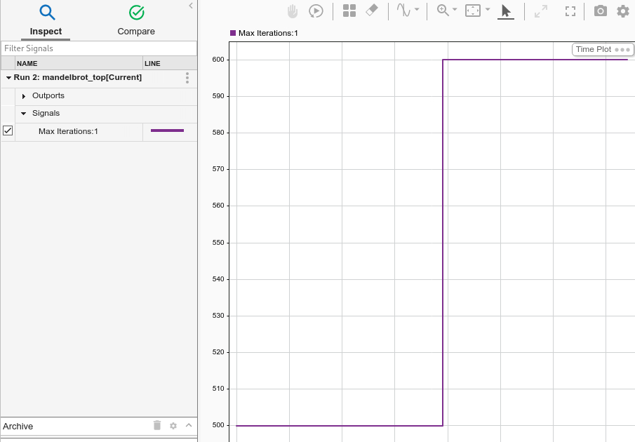
View the logged signals by clicking on the Simulation Data Inspector button in the Hardware tab. The Simulation Data Inspector appears with the current run open. Select the signals to view in the Inspect pane.
To tune the maximum iterations of the Mandelbrot algorithm, double-click on the Constant block while the simulation is running in external mode. Set the Constant Value parameter to 600. The Simulation Data Inspector reflects the new value of this parameter.
Note
When performing external mode simulations on Simulink models that contain deep learning networks, a timeout error may occur during
model initialization on the target. This timeout may be because the initialization time
for the executable exceeds the default maximum loading time of 300 seconds. You can
increase the timeout by using the NVIDIA_XCP_EXTMODE_INIT_TIME
environment variable. For example, in the MATLAB Command Window,
enter:
setenv('NVIDIA_XCP_EXTMODE_INIT_TIME','500');
Disconnect from and Reconnect to Target Application
To disconnect from the application without stopping it, on the Hardware tab, in the Run on Hardware section, click Monitor & Tune. Then, under Step By Step Commands, click Disconnect. To reconnect to the application, under Step By Step Commands, click Connect.
Stop Target Application
To simultaneously disconnect Simulink from the target and end execution of the target application, on the Hardware tab, in the Run on Hardware section, click Stop.
See Also
Functions
open_system(Simulink) |load_system(Simulink) |save_system(Simulink) |close_system(Simulink) |bdclose(Simulink) |get_param(Simulink) |set_param(Simulink) |sim(Simulink) |slbuild(Simulink)
Topics
- Accelerate Simulation Speed by Using GPU Coder
- Code Generation from Simulink Models with GPU Coder
- GPU Code Generation for Deep Learning Networks Using MATLAB Function Block
- GPU Code Generation for Blocks from the Deep Neural Networks Library
- Targeting NVIDIA Embedded Boards
- Numerical Equivalence Testing