Design Cooke Triplet
This example shows how to design a Cooke triplet lens system. This example requires the Optical Design and Simulation Library for Image Processing Toolbox™. You can install the Optical Design and Simulation Library for Image Processing Toolbox from Add-On Explorer. For more information about installing add-ons, see Get and Manage Add-Ons.
The Cooke triplet is a lens design that is useful in photography and optical instruments because of its simple construction, consisting of just three lenses, and its capability for comprehensive aberration correction. This design can effectively address basic chromatic aberrations and all five primary monochromatic aberrations.
Spherical aberration
Coma
Astigmatism
Field curvature
Distortion
The Cooke triplet can be useful when you need simplicity, cost-effectiveness, durability, and good performance over a medium field of view in your lens design.
The Cooke triplet consists of three separate lenses: two outer biconvex (converging) lenses and a biconcave (diverging) lens positioned between them. Typically, the aperture diaphragm is in the space between the second and third lenses. The converging lenses are similar, and are placed at nearly equal distances from the diverging lens. The diverging lens has two refractive surfaces with almost equal radii of curvature. The converging lenses must be made from crown glass, while the diverging lens must be made from flint glass.
Create an Optical System
Create an opticalSystem object named "CookeTriplet".
opsys = opticalSystem(Name="Cooke Triplet");The rest of the example shows how to add optical components to this optical system, trace rays through the optical system, focus the rays through the optical system on an image plane, and create variants of the optical system.
Design First Lens of Triplet
The first lens is a biconvex lens with the two refractive surfaces separated by a thickness of 6.0 mm. The material of the lens must have a refractive index (Nd) of 1.613 and an Abbe number (Vd) of 58.5.
Define the optical material of the lens using the prescribed refractive index and Abbe number. Alternatively, if you already know the name of the glass material, you can select the named glass material from the glass library by using the pickGlass function.
crownMat = opticalMaterial([1.613 58.5],Name="Crown");Add the first refractive surface of the lens to the optical system opsys by using the addRefractiveSurface function. Specify the radius of curvature, the semi-diameter of the lens, and the distance to the next surface. The distance to the next surface is the thickness required between the two refractive surfaces of the lens. Specify the defined optical material crownMat as the material after this refractive surface.
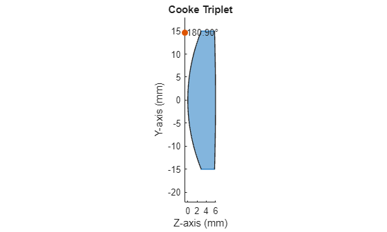
addRefractiveSurface(opsys, ...
    Name="S1", ...
    Radius=40.1, ...
    SemiDiameter=15, ...
    Material=crownMat, ...
    DistanceToNext=6);
Add the second refractive surface of the lens to the optical system opsys. This is the closing surface of the lens. Specify the radius of curvature, the semi-diameter of the lens, and the distance to the next surface. The distance to the next surface is the distance to the next optical component of the optical system. You do not need to specify the optical material, as this is the closing surface of the lens.
addRefractiveSurface(opsys, ...
    Name="S2", ...
    Radius=-537, ...
    SemiDiameter=15, ...
    DistanceToNext=10);
Visualize a 2-D representation of the optical system with the first lens added to the system.
view2d(opsys);
Design Second Lens of Triplet
The second lens must be a biconcave lens with the two refractive surfaces separated by a thickness of 1 mm. The material of the lens must have a refractive index (Nd) of 1.621 and an Abbe number (Vd) of 36.2.
Define the optical material of the lens using the prescribed refractive index and Abbe number.
flintMat = opticalMaterial([1.621 36.2],Name="Flint");Add the first refractive surface of the lens to the optical system opsys. Specify the radius of curvature, the semi-diameter of the lens, and the distance to the next surface. Specify the defined optical material flintMat as the material after this refractive surface.
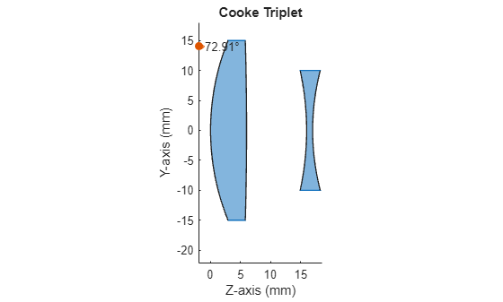
addRefractiveSurface(opsys, ...
    Name="S3", ...
    Radius=-47, ...
    SemiDiameter=10, ...
    Material=flintMat, ...
    DistanceToNext=1);
Add the second refractive surface of the lens to the optical system opsys. This is the closing surface of the lens. Specify the radius of curvature, the semi-diameter of the lens, and the distance to the next surface. The distance to the next surface is the distance to the next optical component of the optical system. You do not need to specify the optical material, as this is the closing surface of the lens.
addRefractiveSurface(opsys, ...
    Name="S4 (STOP)", ...
    Radius=40, ...
    SemiDiameter=10, ...
    DistanceToNext=10.8);
Visualize a 2-D representation of the optical system with the first and second lenses added to the system.
view2d(opsys);
Design Third Lens of Triplet
The third and final lens must be a biconvex lens with the two refractive surfaces separated by a thickness of 5.9 mm. The material of the lens must be the same as that of the first lens.
Add the first refractive surface of the lens to the optical system opsys. Specify the radius of curvature, the semi-diameter of the lens, and the distance to the next surface. Specify the defined optical material crownMat as the material after this refractive surface.
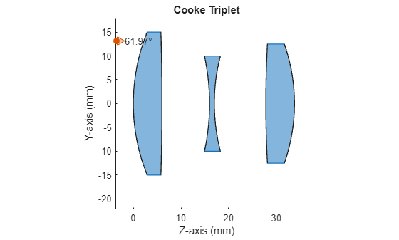
addRefractiveSurface(opsys, ...
    Name="S5", ...
    Radius=234.5, ...
    SemiDiameter=12.5, ...
    Material=crownMat, ...
    DistanceToNext=6);
Add the second refractive surface of the lens to the optical system opsys. This is the closing surface of the lens. Specify the radius of curvature, the semi-diameter of the lens, and the distance to the next surface. The distance to the next surface is the distance to the next optical component of the optical system. You do not need to specify the optical material, as this is the closing surface of the lens.
addRefractiveSurface(opsys, ...
    Name="S6", ...
    Radius=-37.9, ...
    SemiDiameter=12.5, ...
    DistanceToNext=15);
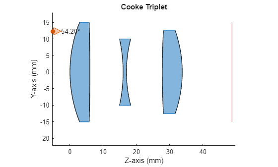
Visualize a 2-D representation of the complete optical system.
view2d(opsys);
Trace and Focus Rays Through Optical System
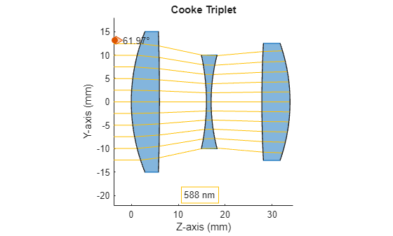
Examine the optical system by tracing rays through it.
Specify the location of a light source, known as a field point, at infinity (on the optical axis) with the rays parallel to the optical axis.
fp = fieldPoint(Angles=[ 0 0]);
Specify the wavelength of the light in nanometers.
wl = optics.constant.Fraunhofer.d;
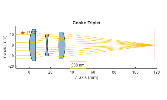
Visualize a 2-D representation of the optical system, and calculate the ray bundle using the defined field point and wavelengths. Add the computed ray bundle to the visualization.
You may modify the field point 'fp' or the wavelength 'wl' to generate and display a new ray bundle for the optical system
rb = traceRays(opsys, FieldPoints=fp, Wavelengths=wl);
h = view2d(opsys);
addRays(h,rb);
Add an image plane to the optical system opsys. The image is intended to form on the image plane.
addImagePlane(opsys,SemiDiameter=15);
Visualize a 2-D representation of the optical system with the image plane, and add the ray bundle to the visualization. Considering the position where the ray bundle converged in the previous visualization, this is not the ideal position for the image plane.
view2d(opsys);
Determine the focal point of the optical system for the generated ray bundle, and move the image plane to the focal point by using the focus function. The focus function adjusts the position of the image plane to minimize the RMS of the spot formed on it.
focus(opsys,FieldPoint=fp,Wavelengths=wl);
Visualize a 2-D representation of the optical system with the image plane moved to the focal point, and add the ray bundle to the visualization. Observe that the ray bundle is now focused on the image plane.
rb = traceRays(opsys,FieldPoints=fp,Wavelengths=wl);
h = view2d(opsys);
addRays(h,rb);
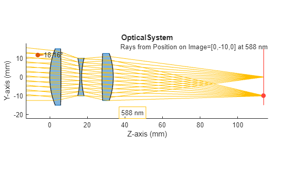
Create Variants of Optical System
You can create different variants of this optical system by using different combinations of parameters. You can modify the radius of curvature, semi-diameter, and material of the lenses, along with the thickness of the lens and the distance between the optical components. When you modify the value of any parameter, the visualization updates to show the updated optical system. To restore the default value for a parameter, right-click the parameter and select Restore Default Value.
opsys = opticalSystem(Name="OpticalSystem"); % Component - 1 (Biconvex Lens) % Add the first surface of the first biconvex lens to the optical system addRefractiveSurface(opsys, ... Name="S1", ... Radius=40.1, ... SemiDiameter=15, ... Material=pickGlass(
"SK16"), ... DistanceToNext=
6) % To complete the first biconvex lens, add a closing surface to the optical system addRefractiveSurface(opsys, ... Name="S2", ... Radius=
-537, ... SemiDiameter=15, ... DistanceToNext=
10) % Component - 2 (Biconcave Lens) % Add the first surface of the biconcave lens to the optical system addRefractiveSurface(opsys, ... Name="S3", ... Radius=
-47, ... SemiDiameter=10, ... Material=pickGlass(
"F2"), ... DistanceToNext=
1) % To complete the biconcave lens, add a closing surface to the optical system addRefractiveSurface(opsys, ... Name="S4 (STOP)", ... Radius=
40, ... SemiDiameter=10, ... DistanceToNext=
10.8) % Component - 3 (Biconvex Lens) % Add the first surface of the second biconvex lens to the optical system addRefractiveSurface(opsys, ... Name="S5", ... Radius=
234.5, ... SemiDiameter=12.5, ... Material=pickGlass(
"SK16"), ... DistanceToNext=
6) % To complete the second biconvex lens, add a closing surface to the optical system addRefractiveSurface(opsys, ... Name="S6", ... Radius=
-37.9, ... SemiDiameter=12.5, ... DistanceToNext=
80) % Add an image plane to the optical system addImagePlane(opsys,SemiDiameter=15) % Define Light source for the optical system fps = fieldPoint(Position=[0
-10],ReferenceFrame="Image"); fps(end+1) = fieldPoint(Angles=[
0 0]); opsys.FieldPoints = fps; wl =
587.5618; opsys.Wavelengths = wl; % Calculate ray bundle for the optical system's field points and % wavelengths rb = traceRays(opsys,FieldPoints=fps,Wavelengths=wl); % Visualize and trace rays through the optical system h = view2d(opsys); addRays(h,rb);
References
[1] Smith, Warren J. "The Cooke Triplet Anastigmat." In Modern Optical Engineering: The Design of Optical Systems, 3rd ed., Chapter 12, Section 12.7. New York: McGraw-Hill, 2000. https://spie.org/Publications/Book/387098.