Contenido principal

opticalSystem

R2026b

Model components of optical system

Since R2026a

    Description

    Add-On Required: This feature requires the Optical Design and Simulation Library for Image Processing Toolbox add-on.

    An opticalSystem object models the components of a physical optical system.

    Create and add components to the optical system using these object functions.

    • addRefractiveSurface — Create and add at least two refractive surfaces, which comprise a lens, to the optical system. To apply a coating to all lenses in the optical system, use the addCoating object function.

    • addImagePlane — Create and add an image plane to the optical system.

    • addImageSensor — Create and add an image sensor to the optical system. Use this object function when you want to render an eSFR or color checker test chart through an optical system.

    • addDiaphragm — Create and add a diaphragm to the optical system.

    • addMirror — Create and add a mirror to the optical system.

    • add — Add an existing component or a set of components to the optical system. To add a gap after adding an optical component using this function, use the addGap object function.

    Specify the coordinate system for the optical axis of the next component to be added, also known as a coordinate break, using the setConstructionFrame object function.

    To modify the components of an existing optical system, such as one imported using the zmximport function, use the changeGap, insert, and remove object functions.

    Analyze optical systems using the opticalSensitivity and opticalTolerance object functions. (since R2026b)

    Creation

    Description

    opsys = opticalSystem creates an empty optical system.

    example

    opsys = opticalSystem(PropertyName=Value) sets writable properties using one or more name-value arguments.

    Properties

    expand all

    Name of the optical system, specified as a scalar or character vector.

    Operational wavelengths, specified as an M-element numeric vector. M is the number of wavelengths. The wavelengths you specify must be positive, and the object sorts them in ascending order.

    Since R2026b

    Weights of operational wavelengths, specified as an M-element numeric vector. M is the number of wavelengths. The wavelength weights you specify must be positive. By default, the weight is 1 for each wavelength. The OpticalSensitivity, OpticalTolerance, SpotRMS, WavefrontRMS, and WavefrontPeakToValley objects normalize the weights to sum to 1 during metric evaluation.

    Index of the primary wavelength, specified as an integer in the range [1, M]. M is the number of wavelengths in the Wavelengths property. By default, the index of the primary wavelength is M/2, rounded up to the nearest integer.

    Ambient material, specified as an opticalMaterial object. The ambient material is the material before the first surface, after the last surface, and in the gap between components, such as air or vacuum. The default ambient material is vacuum.

    Field point representation of a light source or light sources, specified as one of these options:

    FieldPoints valueLight Source Type

    Array of FieldAngle objects

    Field points represent light sources that are at an infinite distance from the first surface of the optical system.

    Array of FieldPosition objects

    Field points represent light sources that are at a finite distance from the first surface of the optical system.
    Array of FieldPosition and FieldAngle objectsField points represent two types of light sources, either at an infinite distance or at a finite distance from the first surface of the optical system.

    To specify light source representations, create field points or arrays of field points using the fieldPoint function.

    Since R2026b

    Weights of field points, specified as an N-element numeric vector. N is the number of field points. The field point weights you specify must be positive. By default, the weight is 1 for each field point. The OpticalSensitivity, OpticalTolerance, SpotRMS, WavefrontRMS, and WavefrontPeakToValley objects normalize the weights to sum to 1 during metric evaluation.

    Object plane, specified as an ObjectPlane object. The object plane serves as the starting point for the light rays that travel through the optical system, and is defined by the position, shape, and tilt angle of a planar surface. By default, the object plane is located at infinity.

    Tilt angle of the optical system, specified as a 3-element row vector. The vector is in the form [θx θy θz], where θx, θy, and θz are tilt angles with respect to the global x, y, and z-axes.

    To learn more about coordinate systems, see Coordinate Systems in Optics.

    Note

    The TiltAngle property represents Euler angles. If you specify angles that are multiples of 90 degrees, visually verify the orientation of the optical system. Gimbal lock can occur, in which two of the three rotational axes become aligned. This alignment results in the loss of one degree of freedom, and can lead to ambiguous or unintended orientations.

    Position of the optical system, specified as a 3-element row vector. The vector is in the form [x y z], where each element is the global x-, y-, and z-coordinate.

    Specify the Position property to select the origin coordinates for the optical system.

    To learn more about coordinate systems, see Coordinate Systems in Optics.

    Local reference frame for the next added component, specified as a 4-by-4 matrix. For the default optical system created using the opticalSystem object, the object positions the component with respect to the global reference frame, and the value of ConstructionFrame is eye(4). To specify the construction reference frame, use the setConstructionFrame object function.

    After you add or remove a component from the optical system, the opticalSystem object updates the ConstructionFrame property to the initial position and tilt angle of the next component.

    To learn more about working with the construction coordinate system, see Coordinate Systems in Optics.

    Custom user data, specified as any data type.

    Optical coatings used in the optical system, represented as an array of opticalCoating objects.

    This property is read-only.

    Materials used in the optical system, represented as an array of opticalMaterial objects.

    This property is read-only.

    Components of the optical system, represented as an array of components. Each element of the array can be a LensElement, Diaphragm, Mirror, ImagePlane, or ObjectPlane object. The order of the components is with respect to the ray propagation along the optical axis, beginning with the light source.

    This property is read-only.

    Flattened components of the optical system, represented as an array of components. If any elements of the Components property are opticalSystem objects, this property flattens them and replaces them with the contents of their corresponding Components properties. The opticalSystem object orders the components with respect to the ray propagation along the optical axis, beginning with the light source.

    This property is read-only.

    Surfaces in the optical system, represented as an array of Surface objects. The opticalSystem object orders them with respect to the ray propagation along the optical axis, beginning with the light source. You can create Surface objects by using the addRefractiveSurface, addMirror, addDiaphragm, or addImagePlane object functions.

    This property is read-only.

    Surface properties for all surfaces in the optical system, represented as a table. The table contains C rows, where C is the number of surfaces in the optical system. The table contains these columns:

    • Radius — Surface radius, represented as a numeric scalar. For biconic surfaces, this value specifies the radius along the x-direction.

    • Shape — Surface shape, specified as a cell array of surface parameters. For circular shapes, the cell contains a scalar semi‑diameter. For rectangular shapes, the cell contains a 1‑by‑2 vector of the form [width height].

    • Position — Surface position, represented as a 3-element row vector.

    • MaterialName — Surface material name, represented as a string scalar.

    • NdVd — Index of refraction and Abbe number of the surface material, represented as a row vector of the form [Nd Vd], where Nd and Vd are the index of refraction and Abbe number, respectively.

    • Surface — Surface, represented as a Surface object.

    • ComponentType — Component type, represented as a string scalar.

    • ComponentIndex — Component index, represented as a positive integer. This value indicates the element of the Components property that corresponds to each surface.

    • FlattenedComponentIndex — Flattened component index, represented as a positive integer. This value indicates the element of the FlattenedComponents property that corresponds to each surface.

    • Component — Component that contains each surface, represented as a LensElement object, a Diaphragm object, a Mirror object, an ImagePlane object, or an ObjectPlane object.

    • Material — Optical material of each surface, stored as an opticalMaterial object.

    Object Functions

    expand all

    addRefractiveSurfaceAdd refractive surface component to optical system
    addImageSensorAdd image sensor to optical system
    addImagePlaneAdd image plane component to optical system
    addDiaphragmAdd physical diaphragm component to optical system
    addMirrorAdd mirror component to optical system
    addGapAdd gap between optical components
    addCoatingAdd optical coating to lens surfaces in optical system
    removeCoatingRemove optical coatings from lens surfaces in optical system
    addAdd optical component to optical system
    setConstructionFrameSet coordinate break for all subsequent components in optical system
    resolveMaterialsResolve component materials in optical system against glass library
    focusPosition image plane of optical system to minimize RMS spot size
    updateSemiDiametersUpdate semi-diameters of surfaces in optical system
    insertInsert optical component into optical system
    removeRemove component from optical system
    changeGapChange gap between components in optical system
    distanceAfterQuery distance after optical component
    distanceBeforeQuery distance before optical component
    halfFieldOfViewCompute half field of view of optical system
    paraxialInfoCompute paraxial information, including cardinal points, for optical system
    traceRaysPerform ray tracing through optical system
    traceDirectedRaysTrace rays from specific origins along specific directions through optical system
    traceAimedRayTrace ray aimed at specific point on target optical surface
    traceChiefRayTrace chief ray through optical system
    traceMarginalRaysTrace marginal rays through optical system
    spotCompute spot at which rays converge in image plane
    psfCompute point spread function of optical system
    mtfCompute modulation transfer function of optical system
    airyDiskRadiusCompute Airy disk radius of diffraction-limited optical system
    fieldCurvatureCompute tangential and sagittal field curvature
    lensDistortionCompute geometric lens distortion for optical system
    rayAberrationCompute tangential and sagittal ray aberration of optical system
    chromaticAberrationCompute lateral and longitudinal chromatic aberration of optical system
    opdOptical path difference for optical system
    opticalSensitivityAnalyze sensitivity of optical system
    opticalToleranceMonte Carlo tolerance analysis of optical system

    Examples

    collapse all

    Create an empty optical system and display its properties.

    opsys = opticalSystem
    opsys = 
      opticalSystem with properties:
    
       Main properties
                          Name: "Optical System"
             PrimaryWavelength: 587.5618
                   Wavelengths: [486.1340 587.5618 656.2810]
             WavelengthWeights: [1 1 1]
                   FieldPoints: [1×1 optics.fieldpoint.FieldAngle]
             FieldPointWeights: 1
                    Components: [0×1 optics.component.Component]
           FlattenedComponents: [0×1 optics.component.Component]
                     Materials: [0×0 opticalMaterial]
                      Surfaces: [0×0 optics.surface.Surface]
                  SurfaceTable: [0×0 table]
    
       Extended properties
                      UserData: []
                   ObjectPlane: [1×1 optics.component.ObjectPlane]
        PrimaryWavelengthIndex: 2
               AmbientMaterial: [1×1 opticalMaterial]
                      Coatings: [0×0 opticalCoating]
             ConstructionFrame: [4×4 double]
                      Position: [0 0 0]
                    TiltAngles: [0 0 0]


    To add a lens component to the optical system, create the two refractive surfaces of the lens using the addRefractiveSurface object function. Specify the lens glass material using the Material name-value argument for the first surface. Specify the center thickness of the lens, in millimeters, using the DistanceToNext name-value argument for the first surface.

    addRefractiveSurface(opsys,Radius=15,Material=[1.74 25.4],DistanceToNext=3)
    addRefractiveSurface(opsys,Radius=-15,DistanceToNext=6.5)

    Add an image plane using the addImagePlane object function.

    addImagePlane(opsys)

    Trace rays through the optical system using the traceRays object function. Specify the ray wavelength as the Fraunhofer d line using the Wavelengths name-value argument.

    rays = traceRays(opsys,Wavelengths=587.5618);

    Display a 2-D visualization of the optical system using the view2d object function. Visualize the traced rays on the displayed optical system using the addRays object function.

    hv = view2d(opsys);
    addRays(hv,rays)
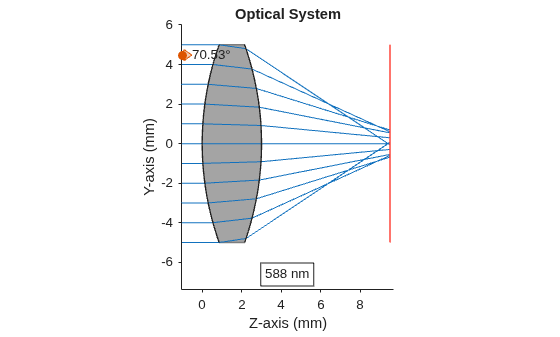
    Figure contains an object of type optics.ui.opticalsystemviewer2d. The chart of type optics.ui.opticalsystemviewer2d has title Optical System.

    Version History

    Introduced in R2026a

    expand all