Six-Step Commutation
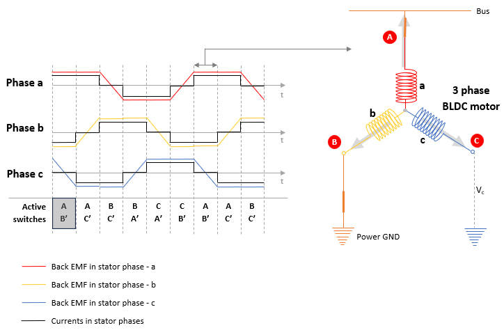
Six-step commutation, also known as trapezoidal control, is a fundamental technique used to drive Brushless DC (BLDC) motors by sequentially energizing their stator phases. The process involves dividing a single electrical revolution into six equal 60-degree segments, with a unique switching state assigned to each interval. During any specific step, two of the three motor phases are energized—one connected to the positive DC bus and the other to the negative—while the third phase remains floating. To maintain synchronization, the controller typically uses Hall-effect sensors to detect the rotor's magnetic position and trigger the transition to the next commutation state. This sequence creates a rotating magnetic field in the stator that pulls the permanent magnet rotor behind it, though the discrete switching inherently produces more torque ripple than sinusoidal methods.
Blocks
Featured Examples

Six-Step Commutation of BLDC Motor Using Sensor Feedback
Use six-step commutation technique to control speed and direction of rotation of a three-phase BLDC motor.
Sensorless Speed Control of BLDC Motor Using Six-Step Commutation
Uses 120-degree conduction mode to implement the six-step commutation technique to control the speed of a three-phase brushless DC (BLDC) motor. The example uses the mechanical speed along with the duty cycles generated by the Sensorless Six-Step Commutation block to control three-phase stator voltages, and therefore, control the rotor speed.