Analyze Motion at Various Parameter Values
This example shows how to use a MATLAB® script to study the dynamic behaviours of a four-bar model at various coupler lengths. The script uses the coupler motion coordinates, obtained using a Transform Sensor block, to plot the resulting coupler curve at each value of the coupler length. For more information about multibody dynamics simulations, see Multibody Dynamics.
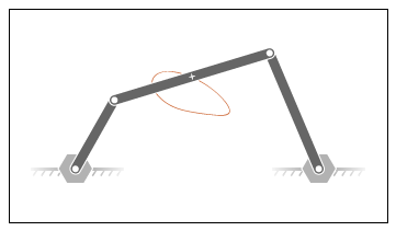
Build Model
At the MATLAB command prompt, enter
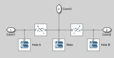
openExample("sm/DocFourBarLinkageModelExample"). A four-bar model opens up. For instructions on how to create this model, see Model a Closed-Loop Kinematic Chain.Under the mask of the Binary Link B block, connect a third Outport block as shown in the figure. You can add an Outport block by copying and pasting Conn1 or Conn2. The new block identifies the frame whose trajectory you plot in this tutorial.
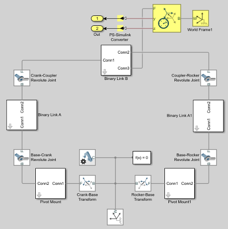
Add the following blocks to the model. During simulation, the Transform Sensor block computes and outputs the coupler trajectory with respect to the world frame.
Library Block Quantity Frames and Transforms World Frame 1 Frames and Transforms Transform Sensor 1 Simscape™ Utilities PS-Simulink Converter 2 Simulink® Sinks Outport 2 In the Transform Sensor block dialog box, select these variables:
Translation > Y
Translation > Z
The block exposes frame ports y and z, through which it outputs the coupler trajectory coordinates.
Connect the blocks as shown in the figure. Be sure to flip the Transform Sensor block so that its base frame port, labeled B, connects to the World Frame block.
Specify Block Parameters
In the Mechanism Configuration block, change Uniform Gravity to
None.In the Base-Crank Revolute Joint block, specify the following velocity state targets. The targets provide an adequate source of motion for the purposes of this tutorial.
Select State Targets > Specify Velocity.
In State Targets > Specify Velocity > Value, enter
2rev/s.Deselect State Target > Specify Position.
Specify the following link lengths. The coupler link length is parameterized in terms of a MATLAB variable,
LCoupler, enabling you change its value iteratively using a simple MATLAB script.Block Parameter Value Binary Link B Length LCoupler Binary Link A1 Length 25 Save the model in a convenient folder, naming it
DocFourBarLinkageModelExampleMsensing.
Create Simulation Script
Create a MATLAB script to iteratively run simulation at various coupler link lengths:
On the MATLAB toolstrip, click New Script.
In the script, enter the following code:
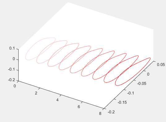
The code runs simulation at nine different coupler link lengths. It then plots the trajectory coordinates of the coupler link center frame with respect to the world frame. Coupler link lengths range from 20 cm to 28 cm.% Run simulation nine times, each time % increasing coupler length by 1 cm. % The original coupler length is 20 cm. for i = (0:8); LCoupler = 20+i; % Simulate model at the current coupler link length (LCoupler), % saving the Outport block data into variables y and z. [~, ~, y, z] = sim('DocFourBarLinkageModelExampleMsensing'); % Plot the [y, z] coordinates of each coupler curve % on the x = i plane. i corresponds to the simulation run number. x = zeros(size(y)) + i; plot3(x, y, z, 'Color', [1 0.8-0.1*i 0.8-0.1*i]); view(30, 60); hold on; end
Save the script as
simFourBarin the folder containing the four-bar model.
Run Simulation Script
Run the simFourBar script. In the MATLAB Editor toolstrip, click the Run button or,
with the editor active, press F5. Multibody
Explorer opens with a dynamic 3-D view of the four-bar model.
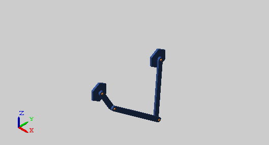
Simscape Multibody™ iteratively runs each simulation, adding the resulting coupler link curve to the active plot. The figure shows the final plot.
You can use the simple approach shown in this tutorial to analyze model dynamics at various parameter values. For example, you can create a MATLAB script to simulate a crank-slider model at different coupler link lengths, plotting for each simulation run the constraint force acting on the piston.