Use SoC Builder to Generate SoC Design
This tutorial shows how to build hardware and software executables for your model and execute your application. Your SoC model can contain a processor model, an FPGA model, or both.
To use SoC Builder, you must install the support package that corresponds to the board you specify in the configuration parameters. For more information, see SoC Blockset Supported Hardware.
Check FPGA and Processor Connection Requirements
You must consider these connection requirements for the FPGA model and the processor model in your top model.
Connect the FPGA model in your top model only to an SoC Blockset™ library block.
If you use a Register Read or Register Write block in the processor model, you must follow one of these options:
Connect these blocks to a DUT port in the FPGA model through a Register Channel block in the top model.
Include an IP Core Register Read block in the FPGA model. You must also include a corresponding Register Write block in the processor model. The Register name parameter in both blocks must match.
If you use a Stream Read block in the processor model, you must connect this block to the DUT in the FPGA model through an AXI4-Stream to Software block in the top model.
If you use a Stream Write block in the processor model, you must connect this block to the DUT in the FPGA model through a Software to AXI4-Stream block in the top model.
Set Up FPGA Design Software Tools
To generate SoC binaries, you must include the path to Vivado® or Quartus® executables on your system path. If the executables are not already in
your system path, use hdlsetuptoolpath function to add them to your
path.
To generate SoC binaries on a Linux® machine, you must install xterm, a terminal emulator for the X Window System, if it is not installed already.
Prepare Model for Generation
Prepare your model for the build process.
Set the Processing Unit parameter in your top model and each referenced model. To set this parameter, open the respective model. Then, in the Simulink® toolstrip, on the System on Chip tab, click Hardware Settings.
In the top model, set Processing Unit to
None.In the FPGA model (if one exists), set Processing Unit to
FPGA.In the processor model (if one exists), set Processing Unit to
APU.
Start the SoC Builder tool. In the Simulink toolstrip, on the System on Chip tab, click Configure, Build & Deploy.
Prepare your model by selecting a starting point for the build process, and then review the model information.
Note
If SoC Builder does not detect a support package installation, SoC Builder first prompts you to install the required support package.
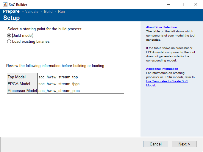
Specify the starting point for the build process. If you are building a model for the first time, select Build model. If you already completed the build process and saved the binaries in a folder, select Load existing binaries.
SoC Builder parses the model and displays the top model, the FPGA model (if one exists), and the processor model (if one exists). Review this information for accuracy. If the information is incorrect, revise the model, save it, and restart the SoC Builder tool.
Note
If your FPGA model is a frame-based Simulink model variant, then SoC Builder does not display the model in the table. To display the model in the table, set the model variant to sample-based and recompile your design.
Click Next.
Select Build Action
Select one of these build actions for your model and automate the build process.
Build, load, and run (default) — Select this option to generate HDL and C code, build software executables, and build an FPGA programming file from your model. After building, SoC Builder loads the generated code to the FPGA board and executes the application.
Build only — Select this option to generate HDL and C code, build software executables and an FPGA programming file from your model. SoC Builder saves the generated binaries in a folder, and you can continue execution later.
Build and load for external mode — Select this option to build the design and run it in external mode. Use external mode to tune parameters on the FPGA without having to rebuild the FPGA design. You can also log data from the FPGA and display it on the host computer. For more information about external mode, see External Mode Simulations for Parameter Tuning, Signal Monitoring, and Code Execution Profiling (Simulink Coder).
Manually configure build process — Select this option to manually proceed through the configuration steps. Clear this option to skip the configuration steps and build your model with fewer clicks. When you clear this option, SoC Builder performs these actions:
Skips the select project folder, configure FPGA parameters, review hardware mapping, and connect hardware steps
Runs the validate model, build model, and load and run application steps
All these steps use the inputs that you provided in the most recent build. If you are running the build process for the first time, SoC Builder uses default inputs for these steps.
Advanced Configuration — Select the build type as one of these options.
Processor and FPGA (default) — Build the processor and FPGA models in your top model.
Processor only — Build only the processor model in your top model.
FPGA only — Build only the FPGA model in your top model.
After you specify the build options, click Next.
Select Project Folder
Specify a path to a project folder by entering the path in the Project Folder text box or by browsing to a folder location. SoC Builder places all the generated files, including reports, executables, and the bitstream, in this specified folder.
If you select Load existing binaries as the starting point for the build process, specify the project folder location of the previous binaries and reports.
Click Next.
Configure FPGA Parameters
Configure these FPGA parameters during the build process.
Include processing system — Select this parameter to include the processing system for processor-based platforms. You must include the processing system when using Embedded Coder® to generate embedded software.
Register configuration clock frequency (MHz) — This clock drives the configuration register interfaces for the vendor IP cores in the generated design.
IP core clock frequency (MHz) — Specify IP core clock frequency in MHz. The IP cores generated using Simulink use this frequency for data path and configuration registers.
Include AXI Manager IP for host-based interaction — Select this parameter to generate a script that interacts with the hardware board.
Include AXI interconnect monitor — Select this parameter to perform memory diagnostics on the hardware board.
Trace capture depth — Specify maximum number of trace entries to be logged in trace mode. To enable this parameter, select Include AXI interconnect monitor.
Note
To enable this step in SoC Builder, you must have an FPGA model in your top model.
Review Hardware Mapping
Open the Hardware Mapping tool by clicking View/Edit.
Review the base addresses and offsets, and edit them if you need to.
Note
To enable the FPGA Addresses entry in the Mapping Browser pane, you must have an FPGA model in your top model. If your FPGA model is set to frame-based modeling, then no FPGA model is visible. In this case, you cannot access FPGA Addresses.
Review the software tasks on the selected hardware board, and edit them if you need to.
Note
To enable the Tasks entry in the Mapping Browser pane, you must have an event-driven task defined in the Task Manager block in your top model.
Review the peripheral parameters for your hardware board, and edit them if you need to.
Note
To enable the Peripherals entry in the Mapping Browser pane, you must have a peripheral block in your model hierarchy.
Click Next.
Validate Model
Check the model against the selected board and generate a report. Check the report to ensure that the design meets your needs.
SoC Builder names the report
modelname_system_reporthtml subfolder of the project folder. The report contains
an overview section with information about the model, project folder, and generated
files. The report also lists your IP cores and vendor-provided IP cores, including the
address map of registers and memory blocks.
Build Model
To generate a bitstream for your FPGA design and a compiled executable for your software, click Build.
Clicking Build opens an external shell and runs third-party tools for synthesis and implementation of the design. The generation time depends on the complexity of your model and your host computer. The software generates the bitstream with the model name you specify. SoC Builder generates a JTAG test bench script if you enable the Include AXI Manager for host-based interaction option in the configuration parameters. The script shows how to set up MATLAB as an AXI Manager and configure your FPGA design over JTAG. You can customize the script to create your own test bench. For more information about using MATLAB as an AXI Manager, see the support package documentation: SoC Blockset Supported Hardware.
SoC Builder generates the host interface script for your FPGA design. The script contains the DUT ports and interface mapping information. Use this script to access the board memory, DUT registers, and AXI4-Stream interfaces from MATLAB. The tool generates these MATLAB files:
gs_modelName_setup— This script adds the AXI4 slave, AXI4-Stream, and memory interfaces. The script also contains DUT port objects that contain the port name, direction, data type, and interface mapping information. The script then maps the DUT ports to the corresponding interfaces.gs_modelName_interface— This script creates a target object, instantiates the setup scriptgs_modelName_setup, and then connects to the target hardware. The script then sends read and write commands to the generated HDL IP core.
For more information about the host interface script, see Host Interface Script Files (HDL Coder).
Note
If you encounter a build error in the external shell while working with
Intel boards, try installing the tee.exe file on your
Windows® machine by following these steps:
Download the
coreutils-5.3.0file for Windows from this link: https://sourceforge.net/projects/gnuwin32/files/coreutils/5.3.0/coreutils-5.3.0.exe/download.Run the
coreutils-5.3.0application and follow the setup steps.Add the
binfolder path to the System variables pane as a Windows environment variable.Right-click the Computer icon and click Properties. Alternatively, in the Windows Control Panel, click System.
Click Advanced system settings.
On the Advanced tab, click Environment Variables.
In the System variables pane, select the Path variable and click Edit.
In the Edit environment variable pane, click New to add a new folder path.
Restart the system.
Run the SoC Builder tool.
Connect Hardware
Review the IPv4 address, SSH Port number, and login credentials. Edit any of these values if necessary. This step is critical if you have more than one board connected to the host computer. SoC Builder requires this information to identify the correct port connection. Verify that the displayed IP address matches the IP address of the board you intend to use.
Verify that the board is connected to the host with an Ethernet cable, and then click Test Connection to test the physical connection to the board.
Note
To enable this step in SoC Builder, you must select Include processing system in the Configure FPGA Parameters step.
Load and Run Application
Note
If your top model includes an FPGA model, but no processor model, the button shows as Load.
Verify that your board is connected to the host computer.
If your top model includes a processor model, connect to the board with an Ethernet cable.
If the top model includes an FPGA model, but no processor model, connect to the board with a JTAG cable.
Click Load and Run. This action loads the generated bitstream to the FPGA, programs the processor, and runs the application.
If you select Tune parameters and monitor signals in external mode in the Select Build Action step, this action loads the bitstream to the FPGA and opens the model in external mode. You can now choose signals for logging and monitoring or change tunable parameters. In the System on Chip tab, in the Run on Hardware section, click Monitor and Tune to run the application on hardware. Click Connect if you already built your design and loaded it onto an FPGA. This action connects your Simulink model to the FPGA model.
SoC Builder packages the project files into a ZIP archive. The packaged zip file contains all the files required to deploy the design onto the hardware board. Unzip this packaged ZIP archive to load and run your design from a different host computer.
See Also
Tools
Objects
fpga(HDL Coder)