Convertidores analógicos-digitales y digitales-analógicos
Utilice estos ejemplos para aprender a diseñar interfaces entre microcontroladores y sistemas físicos, y convierta señales analógicas y digitales.
Ejemplos destacados
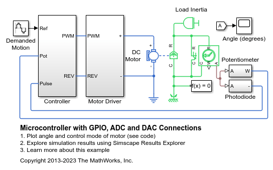
Microcontroller with GPIO, ADC and DAC Connections
Model the interface between a microcontroller unit (MCU) and a physical system. Here the microcontroller's GPIO, ADC and DAC connections are used to control a DC motor and connected load with limited angle travel. Load angle measurement is via a potentiometer sensor. This measurement is calibrated by initially ramping the rotor position until the photodiode detects the zero-angle light pulse from the LED. Once calibrated the MCU commands a 0.1Hz 45 degree amplitude sinusoid.

Delta Sigma ADC with Noise
A simple implementation of a sigma delta analog-to-digital converter. An input in the range 0 to Vref (=1V) is integrated until it causes the integrator to reset. The time to reset is proportional to the input value. Demodulation of the pulses is performed by a low-pass filter. The Asynchronous Sample & Hold block behaves like an edge-triggered D-type flip-flop, passing input U to output Y only on a rising edge of the clock. This model can be used to explore and understand the effect of op-amp impairments such as equivalent input noise on converter accuracy. To turn off the noise, open block Vn and select 'Disabled' for the noise mode.

Switched Capacitor Analog to Digital Converter
How a sigma-delta ADC (analog to digital converter) uses sigma-delta modulation to convert an analog input signal into a digital output signal. The analog input to the sigma-delta ADC controls an oscillator that produces pulses of fixed voltage and duration, but with period between pulses being inversely proportional to the analog input. The oscillator pulses are integrated over a fixed time interval to give a digital representation of the analog input signal.

Filtro analógico antialiasing
Este ejemplo muestra la implementación analógica de un filtro antialiasing para utilizarlo con un convertidor de A a D. La frecuencia de corte del filtro está establecida en 500 Hz para que coincida con la frecuencia de muestreo de 1 kHz del convertidor de A a D. La señal de prueba incorpora una sinusoide de 50 Hz deseada y un componente de mayor frecuencia a 1.100 Hz que no puede capturarse con una frecuencia de muestreo de A a D de 1 kHz. El scope muestra la señal capturada sin y con antialiasing. Con el filtro antialising, la amplitud de la onda sinusoidal de 50 Hz se mide correctamente con una amplitud de 1 y una potencia correspondiente de 0,5 W, es decir, 27 dBm para una carga de referencia de 1 ohmio.