generateSemiconductorSubcircuitROM
Generate reduced-order model of semiconductor switch by running SPICE
Since R2025a
Syntax
Description
The generateSemiconductorSwitchROM function converts a SPICE
subcircuit into a MOSFET (Ideal, Switching) or IGBT (Ideal,
Switching) block, which represents a reduced-order model (ROM). The SPICE
subcircuit can describe any n-type semiconductor device with an integral diode. The function
parameterizes the ROM with the on-state tabulated I-V curve and tabulated switching losses for
the transistor, and with the on-state tabulated I-V curve and tabulated reverse recovery loss
for the associated body diode.
Manufacturers often provide SPICE subcircuits that you can use to parameterize Simscape
blocks. One option is to generate a lookup table to parameterize a high-fidelity
N-Channel MOSFET or N-Channel
IGBT block from a SPICE netlist using the ee.spice.semiconductorSubcircuit2lookup function. ROMs are easier to interpret
and run faster than high-fidelity semiconductor switch subsystems. Use ROMs to quickly test
and analyze system-level scenarios where the semiconductor switch interacts with other
systems.
To use this function, you need a SPICE simulation engine. The function supports:
SIMetrix 8.4 and beyond — You must be able to run SIMetrix in non-GUI Mode. For more information, see Running in non-GUI Mode (SIMetrix Simulator Reference).
LTspice XVII and beyond.
generateSemiconductorSubcircuitROM(
generates a ROM from the SPICE subcircuit named libraryPath,subcircuitName)subcircuitName in the
SPICE subcircuit library file on the path libraryPath.
generateSemiconductorSubcircuitROM(
specifies options using one or more name-value arguments in addition to the input arguments
in the previous syntax. For example,
libraryPath,subcircuitName,Name=Value)generateSemiconductorSubcircuitROM(libraryPath,subcircuitName,OnStateGateSourceVoltage=20)
generates a ROM with an on-state gate-source voltage equal to 20 V.
Some of the name-value arguments are the test-circuit conditions. You can set these values based on your detailed circuit conditions or a datasheet. These values are optional, but accurate test-circuit conditions provide you with more accurate ROMs.
ROMParameters = generateSemiconductorSubcircuitROM(libraryPath,subcircuitName,Name=Value)
Examples
Since R2026a
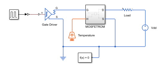
This example shows how to generate a Simscape reduced order model (ROM) from a SPICE defined MOSFET by using the function generateSemiconductorSubcircuitROM. The function runs the necessary simulations using LTspice or SIMetrix software.
In this example, you use the values in the manufacturer data sheet of the MOSFET C3M0032120D to define the input arguments of the generateSemiconductorSubcircuitROM function.
Define Input Arguments
Define the input arguments for the generateSemiconductorSubcircuitROM function based on the SPICE simulation tool and operating system.
Define the name of the library that contains the subcircuit to simulate.
filename = "C3M0032120D.lib";Define the name of the SPICE subcircuit inside the library file.
subcircuitName = "C3M0032120D";Define the SPICE software used during the simulation. By default, the function uses SIMetrix.
SPICETool = "LTspice";Define the path of the executable of the SPICE tool used during simulation. The default value is C:\Program Files\SIMetrix910\bin64\Sim.exe. If you are not using a Windows® operating system, or if the path is not the default specified before, this argument is needed.
SPICEPath = "C:\Users\"+ getenv('USERNAME') + "\AppData\Local\Programs\ADI\LTspice\LTspice.exe";
Define the folder for the generated netlists and SPICE outputs.
netlistFolderPath = "SPICENetlists";Define the vector of terminal orders. The values of this vector define the ports of the semiconductor device to which each node of the SPICE subcircuit connects. For example, observe the definition of the subckt C3M0032120D d g s Tj Tc subcircuit in the library file. The subcircuit defines the nodes for the drain, gate, source, junction temperature, and case temperatures at the positions 1, 2, 3, 4, and 5, respectively. The generateSemiconductorSubcircuitROM function requires you to use the number 1 for the drain, 2 for the gate, 3 for the source, 4 for the base, 5 for the junction temperature, and 0 for no connection. To obtain a ROM, you do not need the case temperature. Use this vector of terminal orders for this MOSFET.
terminals = [1 2 3 5 0];
Define the device type. In this example, the device is a MOSFET.
deviceType = 'MOSFET';Define the on-state gate-source voltage. Set this argument equal to the gate driver on-state voltage in the destination circuit. To decide the value of it, look at the manufacturer data sheet. The function assigns the value of this argument to the MOSFET gate node. The value of this argument must be within the data sheet limits and greater than the threshold voltage. The threshold voltage of an C3M0032120D MOSFET is equal to 2.5 V and the maximum operational gate-source voltage is equal to 19 V. You can find the threshold voltage value in the Gate Threshold Voltage parameter in the Electrical Characteristic table, and the gate-source voltage value in the Operational Gate-Source Voltage parameter of the Key Parameters table. Specify a value of 10 V for the on-state gate-source voltage.
VgsOn = 10;
Define the off-state gate-source voltage. Set this argument equal to the gate driver off-state voltage in the destination circuit. It must be less than the threshold voltage and greater than the minimum allowed voltage. By default, this value is equal to 0.
VgsOff = 0;
Define the constant current for threshold voltage. The function uses this current value to obtain the switch threshold voltage by measuring the gate voltage at which a constant drain current is first observed. This current is typically very small. The data sheet specifies a value of 15 mA. You can find this information in the Test Conditions column of the Gate Threshold Voltage parameter in the Electrical Characteristic table.
Icc = 0.0115;
Define the on-state gate resistance. The data sheet specifies a value of 5 . You can find this information in the Internal Gate Resistance row of the Electrical Characteristics table.
RgOn = 5;
Define the off-state gate resistance. The manufacturer data sheet does not specify a value for this argument. Specify the same value as the on-state gate resistance.
RgOff = 5;
You must specify values within the manufacturer operating range, which for this device is between -55 and 150°C. For this example, choose temperature points of 25 and 75°C.
TVec = [25 75];
Define the on-state current breakpoints for the tabulated I-V curve. This argument specifies the currents at which the function tabulates the device. The values of this argument must be less than the maximum data sheet values, which you can find in the DC Continuous Drain Current parameter of the Key Parameters table.
Define the on-state current breakpoints for switching losses.
IVec = 5:10:45;
Define the off-state voltage breakpoints for switching losses. These values define the voltage breakpoints at which the function tabulates the device diode. The value of this argument must be less than the maximum values. You can find the maximum value in the Drain-Source Voltage parameter of the Key Parameters table.
VVec = [10 50];
Define the gate voltage rise and fall time. The value should be smaller than the turn-on and turn-off time of the device. You can find the values in the Electrical Characteristics table.
GateVoltageRiseFallTimeForLoss = 10e-9;
Adjust these values depending on the circuit where you will use the device. The data sheet does not specify the leakage inductance or stray capacitance, and the final circuit is undetermined in this case. Assume default values of zero.
Lleak = 0;
Cstray = 0;
Generate Reduced Order Model
Generate the ROM.
generateSemiconductorSubcircuitROM(filename, subcircuitName,...
    "SPICETool", SPICETool, "SPICEPath", SPICEPath, "TestNetlistFolder", netlistFolderPath,...
    "OnStateGateSourceVoltage", VgsOn, "OffStateGateSourceVoltage", VgsOff,...
    "ConstantCurrentForThresholdVoltage", Icc, "OnStateGateResistance", RgOn,...
    "OffStateGateResistance", RgOff, "Temperatures", TVec,  ...
    "OnStateCurrentsForIV", IVec, "OnStateCurrentsForLoss", IVec,...
    "OffStateVoltagesForLoss", VVec, "GateVoltageRiseFallTimeForLoss", GateVoltageRiseFallTimeForLoss,...
    "TestCircuitLeakageInductance", Lleak, "TestCircuitStrayCapacitance", Cstray);
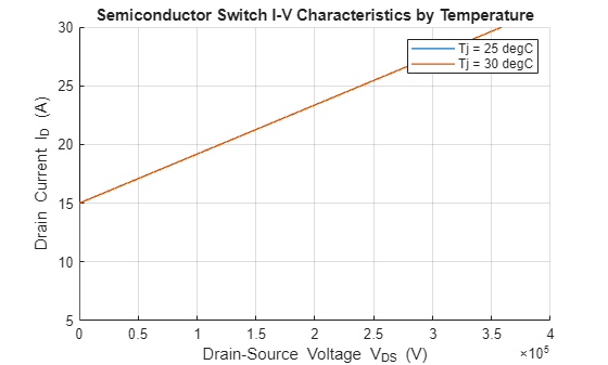
Using:
  DeviceType = MOSFET
  Terminals = [1;2;3;5;0]
  OnStateGateSourceVoltage = 10
  OffStateGateSourceVoltage = 0
  ConstantCurrentForThresholdVoltage = 0.0115
  OnStateGateResistance = 5
  OffStateGateResistance = 5
  Temperatures = [25;75]
  OnStateCurrentsForIV = [5;15;25;35;45]
  OnStateCurrentsForLoss = [5;15;25;35;45]
  OffStateVoltagesForLoss = [10;50]
  MaximumSwitchingFrequency = 100000
  GateVoltageRiseFallTimeForLoss = 1e-08
  TestCircuitLeakageInductance = 0
  TestCircuitStrayCapacitance = 0
  Reltol = 0.001
  Abstol = 1e-12
  Vntol = 1e-06
  Gmin = 1e-12
  Cshunt = 0
  SingleSimulationTimeLimit = 100
Extracting switch IV curve ...
Using existing netlist SPICENetlists\C3M0032120D_Vth_I0A0115_T25.net to extract threshold voltage.
Running netlist SPICENetlists\C3M0032120D_Vth_I0A0115_T25.net to extract threshold voltage in SPICE tool LTspice ...
Using existing netlist SPICENetlists\C3M0032120D_SwitchIV_Vg10_I45.net to extract switch current-voltage table.
Running netlist SPICENetlists\C3M0032120D_SwitchIV_Vg10_I45.net to extract switch current-voltage table in SPICE tool LTspice ...
Using existing netlist SPICENetlists\C3M0032120D_Goff_T25.net to extract off-conductance.
Running netlist SPICENetlists\C3M0032120D_Goff_T25.net to extract off-conductance in SPICE tool LTspice ...
![Figure contains an axes object. The axes object with title Semiconductor Switch I-V Characteristics by Temperature, xlabel Drain-Source Voltage Vds [V], ylabel Drain-Source Current Ids [A] contains 2 objects of type line. These objects represent Tj = 25 degC, Tj = 75 degC.](../../examples/simscapeelectrical/win64/GenerateMOSFETSubcircuitROMExample_01.png)
Extracting diode IV curve ...
Using existing netlist SPICENetlists\C3M0032120D_DiodeIV.net to extract diode current-voltage table.
Running netlist SPICENetlists\C3M0032120D_DiodeIV.net to extract diode current-voltage table in SPICE tool LTspice ...
![Figure contains an axes object. The axes object with title Diode I-V Characteristics by Temperature, xlabel Diode forward voltage Vf [V], ylabel Diode forward current If [A] contains 2 objects of type line. These objects represent Tj = 25 degC, Tj = 75 degC.](../../examples/simscapeelectrical/win64/GenerateMOSFETSubcircuitROMExample_02.png)
Extracting switching loss lookup tables ...
Using existing netlist SPICENetlists\C3M0032120D_Loss_V10_T25.net to extract diode reverse recovery loss table.
Using existing netlist SPICENetlists\C3M0032120D_Loss_V50_T25.net to extract diode reverse recovery loss table.
Using existing netlist SPICENetlists\C3M0032120D_Loss_V10_T75.net to extract diode reverse recovery loss table.
Using existing netlist SPICENetlists\C3M0032120D_Loss_V50_T75.net to extract diode reverse recovery loss table.
Running netlist SPICENetlists\C3M0032120D_Loss_V10_T25.net to extract losses in SPICE tool LTspice.
Running netlist SPICENetlists\C3M0032120D_Loss_V50_T25.net to extract losses in SPICE tool LTspice.
Running netlist SPICENetlists\C3M0032120D_Loss_V10_T75.net to extract losses in SPICE tool LTspice.
Running netlist SPICENetlists\C3M0032120D_Loss_V50_T75.net to extract losses in SPICE tool LTspice.
![Figure Eon contains 2 axes objects. Axes object 1 with title Turn-On Switching Loss (Eon) at Tj = 25 [degC], xlabel On-State Current [A], ylabel Energy Loss (Eon) [J] contains 3 objects of type line. These objects represent On-State Voltage = 0 [V], On-State Voltage = 10 [V], On-State Voltage = 50 [V]. Axes object 2 with title Turn-On Switching Loss (Eon) at Tj = 75 [degC], xlabel On-State Current [A], ylabel Energy Loss (Eon) [J] contains 3 objects of type line. These objects represent On-State Voltage = 0 [V], On-State Voltage = 10 [V], On-State Voltage = 50 [V].](../../examples/simscapeelectrical/win64/GenerateMOSFETSubcircuitROMExample_03.png)
![Figure Eoff contains 2 axes objects. Axes object 1 with title Turn-Off Switching Loss (Eoff) at Tj = 25 [degC], xlabel Off-State Current [A], ylabel Energy Loss (Eoff) [J] contains 3 objects of type line. These objects represent Off-State Voltage = 0 [V], Off-State Voltage = 10 [V], Off-State Voltage = 50 [V]. Axes object 2 with title Turn-Off Switching Loss (Eoff) at Tj = 75 [degC], xlabel Off-State Current [A], ylabel Energy Loss (Eoff) [J] contains 3 objects of type line. These objects represent Off-State Voltage = 0 [V], Off-State Voltage = 10 [V], Off-State Voltage = 50 [V].](../../examples/simscapeelectrical/win64/GenerateMOSFETSubcircuitROMExample_04.png)
![Figure Erec contains 2 axes objects. Axes object 1 with title Reverse Recovery Loss (Erec) at Tj = 25 [degC], xlabel Complementary Switch Initial Current [A], ylabel Energy Loss (Erec) [J] contains 3 objects of type line. These objects represent Off-State Voltage = 0 [V], Off-State Voltage = 10 [V], Off-State Voltage = 50 [V]. Axes object 2 with title Reverse Recovery Loss (Erec) at Tj = 75 [degC], xlabel Complementary Switch Initial Current [A], ylabel Energy Loss (Erec) [J] contains 3 objects of type line. These objects represent Off-State Voltage = 0 [V], Off-State Voltage = 10 [V], Off-State Voltage = 50 [V].](../../examples/simscapeelectrical/win64/GenerateMOSFETSubcircuitROMExample_05.png)
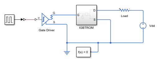
This example shows how to generate a Simscape reduced-order model (ROM) of a SPICE-defined IGBT by using the generateSemiconductorSubcircuitROM function. The function runs the necessary simulations using LTspice or SIMetrix software.
In this example, you use the values in the manufacturer datasheet of the IGBT IKW15N120T2 [1] to define the input arguments of the generateSemiconductorSubcircuitROM function.
Define Input Arguments
Define the input arguments for the generateSemiconductorSubcircuitROM function based on the SPICE simulation tool and operating system.
Define the name of the library that contains the subcircuit to simulate.
filename = "IGBT_1200V_TRENCHSTOP2_L1.lib";Define the name of the SPICE subcircuit inside the library file.
subcircuitName = "IKW15N120T2_L1";Define the SPICE software used during the simulation. By default, the function uses SIMetrix.
SPICETool = "LTspice";Define the path of the executable of the SPICE tool used during simulation. The default value is C:\Program Files\SIMetrix910\bin64\Sim.exe. If you are not using a Windows® operating system, or if the path is not the default specified before, this argument is needed.
SPICEPath = "C:\Users\"+ getenv('USERNAME') + "\AppData\Local\Programs\ADI\LTspice\LTspice.exe";
Define the folder for the generated netlists and SPICE outputs.
netlistFolderPath = "SPICENetlists";Define the vector of terminal orders. The values of this vector define the ports of the semiconductor device to which each node of the SPICE subcircuit connects. For example, observe the definition of the .SUBCKT IKW15N120T2_L1 C G E PARAMS: TJ= {TEMP} subcircuit in the library file. The subcircuit defines the nodes for the drain, gate, source, junction temperature, and case temperatures at the positions 1, 2, 3, 4, and 5, respectively. The generateSemiconductorSubcircuitROM function requires you to use the number 1 for the drain, 2 for the gate, 3 for the source, 4 for the base, 5 for the junction temperature, and 0 for no connection. To obtain a ROM, you do not need the case temperature and you cannot assign the junction temperature for this IGBT device. Use this vector of terminal orders for this IGBT.
terminals = [1 2 3];
Define the device type. In this example, the device is an IGBT.
deviceType = 'IGBT';Define the on-state gate-source voltage. To decide the value of this argument, look at the manufacturer datasheet. The function assigns the value of this argument to the IGBT gate node. The value of this argument must be within the datasheet limits and greater than the threshold voltage. For an IGBT, the source is called emitter. The threshold voltage of an IKW15N120T2 IGBT is equal to 6.4 V and the maximum operational gate-source voltage is equal to 20 V. You can find the threshold voltage value in the Gate-emitter threshold voltage parameter in the Electrical Characteristic table, and the gate-source voltage value in the Gate-emitter voltage parameter of the Maximum Ratings table. Specify a value of 10 V for the on-state gate-source voltage.
VgeOn = 15;
Define the off-state gate-source voltage. This argument must be less than the threshold voltage and greater than the minimum allowed voltage. By default, this value is equal to 0.
Define the constant current for threshold voltage. The function uses this current value to obtain the switch threshold voltage by measuring the gate voltage at which a constant drain current is first observed. This current is typically very small. The datasheet specifies a value of 0.6 mA. You can find this information in the Conditions column of the Gate-emitter threshold voltage parameter in the Electrical Characteristic table.
Icc = 0.6e-3;
Define the on-state gate resistance. The datasheet specifies a value of 41.8 ohms. You can find this information in the conditions from Figure 1 of the datasheet.
RgOn = 41.8;
Define the off-state gate resistance. The manufacturer datasheet does not specify a value for this argument. Specify the same value as the on-state gate resistance.
RgOff = 41.8;
Define the temperature point at which the device is tabulated. You must specify the values of this argument within the manufacturer operating ranges. In this example, you cannot parameterize the device over the temperature because the input terminals do not include the junction temperature. Specify values close to 27 °C, which is the default value for LTspice.
TVec = [25 30];
Define the on-state current breakpoints for the tabulated I-V curve. This argument specifies the currents at which the function tabulates the device. The values of this argument must be less than the maximum datasheet values, which you can find in the DC collector current parameter of the Maximum Ratings table.
IVec = [0:0.5:2, 5:5:20];
Define the on-state current breakpoints for switching losses.
Define the off-state voltage breakpoints for switching losses. These values define the voltage breakpoints at which the function tabulates the device diode. The values of this argument must be less than the maximum values.
VVec = 10:200:610;
Define the leakage inductance and stray capacitance of test circuit. The datasheet specifies the leakage inductance of 315 nH and stray capacitance of 34 pF. You can find the information in the Conditions column of the IGBT Characteristic table.
Lleak = 315e-9;
Cstray = 34e-12;
Generate ROM
If you have a supported SPICE simulation tool installed, generate the ROM.
generateSemiconductorSubcircuitROM(filename,subcircuitName,...
    SPICETool=SPICETool,SPICEPath=SPICEPath,TestNetlistFolder=netlistFolderPath,...
    DeviceType=deviceType,Terminals=terminals,OnStateGateSourceVoltage=VgeOn,...
    ConstantCurrentForThresholdVoltage=Icc,OnStateGateResistance=RgOn,...
    OffStateGateResistance=RgOff,Temperatures=TVec,...
    OnStateCurrentsForIV=IVec,OnStateCurrentsForLoss=IVec,...
    OffStateVoltagesForLoss=VVec,TestCircuitLeakageInductance=Lleak,...
    TestCircuitStrayCapacitance=Cstray);
Using:
  DeviceType = IGBT
  Terminals = [1;2;3]
  OnStateGateSourceVoltage = 15
  OffStateGateSourceVoltage = 0
  ConstantCurrentForThresholdVoltage = 0.0006
  OnStateGateResistance = 41.8
  OffStateGateResistance = 41.8
  Temperatures = [25;30]
  OnStateCurrentsForIV = [0;0.5;1;1.5;2;5;10;15;20]
  OnStateCurrentsForLoss = [0;0.5;1;1.5;2;5;10;15;20]
  OffStateVoltagesForLoss = [10;210;410;610]
  MaximumSwitchingFrequency = 100000
  TestCircuitLeakageInductance = 3.15e-07
  TestCircuitStrayCapacitance = 3.4e-11
  Reltol = 0.001
  Abstol = 1e-12
  Vntol = 1e-06
  Gmin = 1e-12
  Cshunt = 0
Extracting switch IV curve ...
Using existing netlist SPICENetlists\IKW15N120T2_L1_Vth_I0A0006_T25.net to extract threshold voltage.
Running netlist SPICENetlists\IKW15N120T2_L1_Vth_I0A0006_T25.net to extract threshold voltage in SPICE tool LTspice.
Using existing netlist SPICENetlists\IKW15N120T2_L1_SwitchIV_Vg15_I20.net to extract switch current-voltage table.
Running netlist SPICENetlists\IKW15N120T2_L1_SwitchIV_Vg15_I20.net to extract switch current-voltage table in SPICE tool LTspice.
Using existing netlist SPICENetlists\IKW15N120T2_L1_Goff_T25.net to extract off-conductance.
Running netlist SPICENetlists\IKW15N120T2_L1_Goff_T25.net to extract off-conductance in SPICE tool LTspice.
Extracting diode IV curve ...
Using existing netlist SPICENetlists\IKW15N120T2_L1_DiodeIV.net to extract the diode current-voltage table.
Running netlist SPICENetlists\IKW15N120T2_L1_DiodeIV.net to extract diode current-voltage table in SPICE tool LTspice.
![Figure contains an axes object. The axes object with title Diode I-V Characteristics by Temperature, xlabel Diode forward voltage V indexOf f baseline [V], ylabel Diode forward current I indexOf f baseline [A] contains 2 objects of type line. These objects represent Tj = 25 degC, Tj = 30 degC.](../../examples/simscapeelectrical/win64/GenerateIGBTSubcircuitROMExample_02.png)
Extracting switching loss lookup tables ...
Using existing netlist SPICENetlists\IKW15N120T2_L1_Loss_V10_T25.net to extract losses.
Using existing netlist SPICENetlists\IKW15N120T2_L1_Loss_V210_T25.net to extract losses.
Using existing netlist SPICENetlists\IKW15N120T2_L1_Loss_V410_T25.net to extract losses.
Using existing netlist SPICENetlists\IKW15N120T2_L1_Loss_V610_T25.net to extract losses.
Using existing netlist SPICENetlists\IKW15N120T2_L1_Loss_V10_T30.net to extract losses.
Using existing netlist SPICENetlists\IKW15N120T2_L1_Loss_V210_T30.net to extract losses.
Using existing netlist SPICENetlists\IKW15N120T2_L1_Loss_V410_T30.net to extract losses.
Using existing netlist SPICENetlists\IKW15N120T2_L1_Loss_V610_T30.net to extract losses.
Running netlist SPICENetlists\IKW15N120T2_L1_Loss_V10_T25.net to extract losses in SPICE tool LTspice.
Running netlist SPICENetlists\IKW15N120T2_L1_Loss_V210_T25.net to extract losses in SPICE tool LTspice.
Running netlist SPICENetlists\IKW15N120T2_L1_Loss_V410_T25.net to extract losses in SPICE tool LTspice.
Running netlist SPICENetlists\IKW15N120T2_L1_Loss_V610_T25.net to extract losses in SPICE tool LTspice.
Running netlist SPICENetlists\IKW15N120T2_L1_Loss_V10_T30.net to extract losses in SPICE tool LTspice.
Running netlist SPICENetlists\IKW15N120T2_L1_Loss_V210_T30.net to extract losses in SPICE tool LTspice.
Running netlist SPICENetlists\IKW15N120T2_L1_Loss_V410_T30.net to extract losses in SPICE tool LTspice.
Running netlist SPICENetlists\IKW15N120T2_L1_Loss_V610_T30.net to extract losses in SPICE tool LTspice.
![Figure Eon contains 2 axes objects. Axes object 1 with title Turn-On Switching Loss (Eon) at Tj = 25 [degC], xlabel On-State Current [A], ylabel Energy Loss (Eon) [J] contains 5 objects of type line. These objects represent On-State Voltage = 0 [V], On-State Voltage = 10 [V], On-State Voltage = 210 [V], On-State Voltage = 410 [V], On-State Voltage = 610 [V]. Axes object 2 with title Turn-On Switching Loss (Eon) at Tj = 30 [degC], xlabel On-State Current [A], ylabel Energy Loss (Eon) [J] contains 5 objects of type line. These objects represent On-State Voltage = 0 [V], On-State Voltage = 10 [V], On-State Voltage = 210 [V], On-State Voltage = 410 [V], On-State Voltage = 610 [V].](../../examples/simscapeelectrical/win64/GenerateIGBTSubcircuitROMExample_03.png)
![Figure Eoff contains 2 axes objects. Axes object 1 with title Turn-Off Switching Loss (Eoff) at Tj = 25 [degC], xlabel Off-State Current [A], ylabel Energy Loss (Eoff) [J] contains 5 objects of type line. These objects represent Off-State Voltage = 0 [V], Off-State Voltage = 10 [V], Off-State Voltage = 210 [V], Off-State Voltage = 410 [V], Off-State Voltage = 610 [V]. Axes object 2 with title Turn-Off Switching Loss (Eoff) at Tj = 30 [degC], xlabel Off-State Current [A], ylabel Energy Loss (Eoff) [J] contains 5 objects of type line. These objects represent Off-State Voltage = 0 [V], Off-State Voltage = 10 [V], Off-State Voltage = 210 [V], Off-State Voltage = 410 [V], Off-State Voltage = 610 [V].](../../examples/simscapeelectrical/win64/GenerateIGBTSubcircuitROMExample_04.png)
![Figure Erec contains 2 axes objects. Axes object 1 with title Reverse Recovery Loss (Erec) at Tj = 25 [degC], xlabel Complementary Switch Initial Current [A], ylabel Energy Loss (Erec) [J] contains 5 objects of type line. These objects represent Off-State Voltage = 0 [V], Off-State Voltage = 10 [V], Off-State Voltage = 210 [V], Off-State Voltage = 410 [V], Off-State Voltage = 610 [V]. Axes object 2 with title Reverse Recovery Loss (Erec) at Tj = 30 [degC], xlabel Complementary Switch Initial Current [A], ylabel Energy Loss (Erec) [J] contains 5 objects of type line. These objects represent Off-State Voltage = 0 [V], Off-State Voltage = 10 [V], Off-State Voltage = 210 [V], Off-State Voltage = 410 [V], Off-State Voltage = 610 [V].](../../examples/simscapeelectrical/win64/GenerateIGBTSubcircuitROMExample_05.png)
References
[1] Infineon. “IKW15N120T2. TrenchStop® 2nd generation Series.” Accessed Jan 9, 2024. https://www.infineon.com/assets/row/public/documents/60/49/infineon-ikw15n120t2-datasheet-en.pdf?fileId=db3a304412b407950112b426d2d43acd.
Input Arguments
Name-Value Arguments
Output Arguments
Tips
If you set the value of the
SPICEToolargument to'SIMetrix', thegenerateSemiconductorSwitchROMfunction uses the value of theGateVoltageRiseFallTimeForLossargument to estimate a value for the interval at which SIMetrix prints output,tstep. Iftstepis too small, SIMetrix takes longer to write output and MATLAB takes longer to read it. Iftstepis too large, the temporal resolution is too low for the function to extract losses accurately. You can adjust the step time by modifying the value oftstepin the generated netlist. For example, this code block shows a generated netlist with a step time of 2 ns. To modify the step time, replace2.000000e-09with the value of the new step time in seconds.* SIMetrix syntax to perform a transient analysis * .tran tstep tstop * You can adjust 'tstep' to modify the output interval for tabulated results specified by the '.PRINT' statement .tran 2.000000e-09 1.000000e-04 sweep single param lossLoadCurrent list 10 20 30 40 50
After you make manual edits, save the generated netlist.
The
generateSemiconductorSwitchROMfunction uses the value of theGateVoltageRiseFallTimeForLossargument to estimate an appropriate stop time for the transient simulation of the loss extraction circuit. However, you can adjust the stop time by editing the generated netlist. In the SPICE directive for transient simulation, adjust the value assigned tostopTimeand the value of<Tstop>in the directive for transient simulation. For example, this code block shows a generated netlist with a stop time of 0.1 ms. To modify the stop time, replace both0.000100and1.000000e-04with the value of the new stop time, in seconds..param stopTime = 0.000100 *.........* .tran 2.000000e-09 1.000000e-04 *.TRAN <Tstep> <Tstop>
After you make manual edits, save the generated netlist.