Implementing Motor Control using Simulink and NXP i.MX RT Crossover Processors
Daniel Popa, NXP
Peter Butko, NXP
Overview
This webinar will show how to design and implement motor control algorithms using Simulink, Embedded Coder, and NXP i.MX RT crossover MCUs. We will introduce Model-Based Design to develop embedded control algorithms and demonstrate an automated path to production implementation on the NXP i.MX RT1060 MCU.
Starting with Field Oriented Control (FOC) algorithms modeled in Simulink, NXP engineers will show how sensorless control of a permanent magnet synchronous motor (PMSM) is implemented. We will use Embedded Coder to generate optimized code from the Simulink model and deploy it to the NXP microcontroller. The code-generation workflow will feature the use of the NXP Model-Based Design Toolbox, which provides an integrated development environment and toolchain for configuring and generating all the necessary software to execute complex applications on NXP MCUs. In addition, Model-Based Design Toolbox includes a Simulink embedded target for NXP MCUs and peripheral device blocks and drivers.
Highlights
- Implementing a permanent magnet synchronous motor (PMSM) with sensorless Field Oriented Control (FOC)
- Generating optimized, production ready code with Embedded Coder
- Deploying code to an NXP i.MX RT1060 MCU using the NXP Model-Based Design Toolbox
- Configuring peripherals with NXP MCUXpresso® and online application monitoring using NXP FreeMASTER
About the Presenters
Brian McKay is a Technical Marketing Manager specializing in MathWorks solutions for embedded systems customers, including those featuring NXP hardware. He has been building customer solutions that combine MathWorks software with embedded hardware for over 20 years.
Daniel Popa is a Product Manager & Architect, in the Automotive Processing Group at NXP. He graduated from the Politehnica University of Bucharest in Romania with a master’s degree in electrical engineering. He joined NXP in 2008 where he is responsible for Model-Based Design Software solutions for NXP Products.
Peter Butko is a Software Engineer for the NXP Motor control team since 2016. He focuses mainly on permanent magnet synchronous motor (PMSM) advanced control using NXP i.MX RTs crossover processors. Peter received a master’s degree in electric drives and PhD in power electronics from the University of Zilina. His thesis dealt with intelligent drives with asynchronous motors with reduced energy consumption.
Recorded: 30 Jul 2021
Hello, and welcome to this webinar. Implementing motor control using Simulink and NXP i.MX RT crossover processors. I'm Brian McKay from the MathWorks. I'll be joined by Daniel Popa and Peter Butko from NXP.
Our agenda for today. I will start with a very brief overview of motor control and MathWorks motor control blockset. Next, Daniel, from NXP, will do an introduction to NXP model-based design toolbox for i.MX RT crossover processors. Finally, Peter, from NXP, will talk about design and implementation of motor control applications.
So, why are we talking about brushless motors? Well, because they are everywhere. We can find them in electric vehicles, trains, industrial drives, medical devices, and even electric longboards. By using field oriented control, we can digitally control these electric motors. And that's why Simulink and model-based design for developing embedded motor control algorithms can help and accelerate your workflow.
With model based design and Simulink, we can quickly put together a control system and start testing and verifying it in closed loop desktop simulation. This can be done even before motor hardware is available. We provide a way to quickly go from design to implementation by automatically generating code from the Simulink model, and also the ability to use this code to spin a motor.
To minimize development time, we have many reference examples to quickly get started for your next motor control project. And, most importantly, the reason why our customers choose to use Simulink is faster development time.
Motor control blockset lets you design and implement motor control algorithms for permanent magnet synchronous motors. In release R2020B, we made a major upgrade on motor control blockset that will automate and simplify development process for embedded motor control algorithms. Our product provides pre-built algorithmic blocks optimized for generating efficient code.
There are sensor decoders for whole sensor, quadrature encoder and resolver. Sliding mode and flux observer blocks are provided for implementing sensorless control. There are also blocks from motor parameter estimation and automated loop tuning. And, finally, the product provides fully assembled reference examples for sensored and sensorless field-oriented control algorithms.
This webinar is focusing on the deployment to hardware. So please visit the motor control blockset product page on www.mathworks.com. There, you can find many detailed resources and examples on how to use model based design for motor control simulation and testing, using Simulink and motor control blockset.
Here's a quick preview of where we will end up today. This video clip shows a motor control, which was developed in Simulink and integrated with NXP model-based design toolbox. Embedded coder generated highly optimized C code, which is deployed to an i.MX RT 1060 evaluation board connected to a PMSN motor. And the whole project uses Free Master from NXP for debugging and visualization.
Next up is Daniel Popa from NXP. He will tell us about NXP's model-based design tool box, and show us how to get and install it.
Thank you, Brian. Now, in this part of the presentation, we would like to give you an overview of the NXP model-based design toolbox for the i.MX RT crossover microprocessors, and how you can leverage that MATLAB and Simulink capabilities to create ready to run applications.
We shall start with a short overview of the toolbox's main features. Followed by a quick demonstration of the MathWork's environment setup for the NXP hardware enablement. And towards the end of my presentation slot, I'm going to demonstrate an end-to-end application workflow in this newly created environment. So, without further ado, let's see what NXP is offering.
NXP provides a wide range of products designed for industrial consumers and automotive applications. In this presentation, we will focus on the very powerful i.MX RT series of crossover microcontrollers, based on ARM cortex and available evaluation boards that allow you to exercise various functionalities of the microcontrollers. You can find more detailed information about this product in the link below.
Currently, we do offer support for rapid prototyping directly from MATLAB and Simulink for the i.MX RT series highlighted here. Using the current capabilities, you can target applications like motion, lighting, and smart-host control. To create such applications directly from MATLAB or Simulink, you need to install and configure the NXP model-based design toolbox for the i.MX RT microcontrollers.
With this tool box, you can address both model-based design approaches. You can either use it for your own control code design and implementation, by using the export function approach. Or you can design, build, and test the entire software solution using the fully executable approach.
The toolbox is a collection of various NXP tools, runtime drivers, and libraries packaged within a Simulink library that is fully integrated within a MATLAB environment. And delivered with a complete set of examples for each microcontroller peripheral support.
Using an i.MX RT 1060 system diagram, we can easily overlay the Simulink support for various peripherals. Almost all the functionalities that make sense for time-based applications are supported. In addition to those, there is also a set of multimedia applications, like machine vision, voice command, or internet communication, that can be enabled from both MATLAB and Simulink environments.
The NXP model-basaed design toolbox supports various configuration modes and ports, that are listed here. To make the life of our customer easier, we provide additional utilities, like dedicated mathematical and control processing Simulink blocks, real-time debuggers, and additional loaders and IDs supported by MCUXpresso .
Now, some of you might ask, why do you need such an external tool? Why can't you just use MATLAB or Simulink and simply create the application for the NXP target? Apart from MATLAB and Simulink, you need to have additional toolboxes from MathWorks to be able to generate the C code for the application. The most important part here is the embedded code.
Furthermore, you might want to use other optional toolboxes to speed up your design verification and validation. On top of all this, NXP came with this toolbox to compile and deploy the generated codes to the actual. At the same time, the toolbox provides an interface for other NXP runtime software and development tools to plug into the model's ecosystem.
And to be able to use the model's ecosystem on the NXP microcontrollers, you need to download, install, and configure the NXP model-based design toolbox for the hardware part you wish to use. Therefore, let's see very quickly the main steps required to do that.
So first of all, you go to the add-on explorer, you open it, and you search for the NXP. Then, you have a full list of supported packages. You select the microcontrollers that you have. You read all the functionalities, verify if it's suitable for you. Click add, accept the licensing agreement, and that will install the support package. Now, you run this AMP script and you open the installer guide.
The installer guide is designed to walk you step by step on all the necessary setups required to configure the tools. First of all, you sign-in into your NXP account. You select the file that you need. Click agree on the software terms the conditions. And then, you have to download this large mltbx file. Make sure you read and understand all the comments here. You require mltbx extension, so that it's recognized by the MATLAB environment.
Now that you have the file downloaded on your computer, simply select it and the installer will handle the rest of the operations. This is a process that takes a few minutes. You have to be patient here. But once it is installed, you have the option to verify whether or not the installation has been done successfully. Just click on the verify button, and that will inform you whether or not everything was installed correctly.
At this point, you have the option to go and navigate to the folder where the toolbox is installed. And here, I advise you to run this AMP script, highlighted here. This script will perform additional settings and configurations, depending on your MATLAB version that you are using. So once these steps are completed, then the toolbox is ready to be used. And you should see in Simulink's libraries all the blocks available for this microcontroller.
Now that the toolbox is installed, it's quite easy to build the application. All you need to know, is that there are 2 types of NXP blocks. There are configuration and action for input and output commands. In between sits your application or your algorithm, which is typically hardware independent and which can be fully developed with standard MATLAB and Simulink functions.
The NXP Simulink blocks are delivered with a pre-configured set of parameters that are targeted for NXP evaluation boards and are chosen to provide the best experience out-of-the-box. With the default settings, you can have access to various choices supported by each hardware peripheral. But if you plan to use the toolbox as a development tool for the custom hardware design, then NXP has you covered.
We provide the configuration tool capable of exploiting all the NXP hardware capabilities. All you must do is to open the tool, select the New option, save the new configuration, and then the Simulink will load the new settings and use those in the code generation phase.
Now, let's see this workflow in action. I'm going to create a model. This is a standard Simulink model. And let's drag and drop an NXP Simulink block. Let's use an IO block. Once I add this block into the canvas, this will trigger a sequence of events that will allow you to create a default project for the NXP.
So you see here, the Wizard is asking you to choose a default target. By default we are proposing this. But you have the option to choose another evaluation board. Of course, once you choose another one, then the Simulink and our toolbox will create new files, new settings for that. This is a process that takes a few seconds. But once it is completed, it allows you to see all the settings available for the default configuration selected.
Of course, you can do further modification to this configuration within these panels. You can select the load method, you can select various tools, you can see which peripherals are enabled or disabled. And Furthermore, you see what are the default configurations for each peripheral.
You have the option now to return to the Simulink. The project is fully configured and you see the options available within the Simulink block. In this case, you can select various instances and various PINs within those instances. And, depending on the peripheral block, you may have additional options, like simulation or advanced parameters that can be set.
All the settings are available at any time in the parameter step. Right? This is a read-only view that shows you how the tool is configured. So let's suppose I want to add a new PIN here. A new input. How can I do that?
Well, I just click on the configure button. Simulink is going to open the configuration tool. This configuration tool allows you to modify, enable, disable-- to do all sorts of settings within the default configuration. You see what is default enabled. And it has different views. Let's go to the PINs view, and we can see which PINs are enabled in this default configuration.
I can select just the PINs-- the instance-- I'm interested in. I see there are 3 PINs defined as the input. They are the same ones which are available in Simulink. And with these settings, let's say I want to add fourth pin Right? I want to use this one. I can easily transform it into an input. And furthermore, I can associate additional settings with these PINs. Maybe I want to interrupt and other advanced options that are available here.
Furthermore, the configuration tool helps you to see additional information about the speed, the location of the PIN within the microcontrollers, additional identifiers. And at this point, all you have to do is to save your work, save your configuration. Close the tool. And return to the Simulink to process this information.
The Simulink still shows the old version, but once you click the update button it will read the new version of the configuration file. And now allows you access to this newly created PIN. And you can use it in your model as is.
Now this is the input. Now comes the part where you add your own algorithm or your own reference block-- reference model or whatever you want to use. This will be developed with standard Simulink blocks. Right? You don't need to mix any of the NXP Simulink blocks here.
And let's suppose that your algorithm computes something and you want to read or send a command from a peripheral. Let's say we want to read something from the serial, whether or not the pinhas been sent. And that's the kind of application you have to develop.
Now, let's suppose that I want to enable a different peripheral. Something is not enabled. Right? I can look in the peripheral. I see a particular peripheral is disabled. I click on the configure button, once again. And now I can enable that instance for that particular peripheral. Once again, I close it. And now I can see the settings and I can use additional peripherals.
So this is a workflow that you typically do with our tools. And now I'm going to pass it to Peter, and Peter will show you what you have to do to develop motor control application with these kinds of tools.
Thank you, Daniel. Hello, and welcome to everyone. In this part of the presentation, I would like to share with you how sensorless control of a permanent magnet synchronous motor is implemented in MATLAB and Simulink environments.
First, I will share with you the hardware set up used in this presentation. Then, I will show you an FOC block diagram integrated into the Simulink. Next, a very quick section, will be about real time control embedded software libraries, also known as RTCESL. Then, I will show you a Simulink model of a permanent magnet synchronous motor control. And finally, we will look at the demonstration of real motor control.
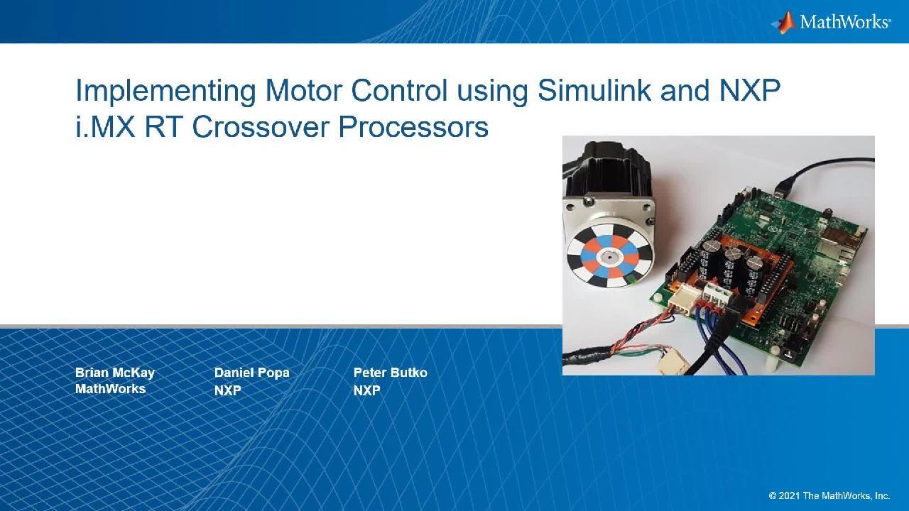
As the base board on our demo, we are using i.MX RT1060 evaluation kit. At its heart, lies the i.MX RT1060 crossover MCU, featuring NXP's advanced implementation of the ARM Cortex-M7 core. This core operates at speeds of up to 600 megahertz, to provide high CPU performance and excellent real-time response.
Inverter plugged directly to the evaluation kit across Arduino connector is freedom motor control all voltage permanent magnet synchronous motor development platform motor. Connected to the inverter is a low voltage permanent magnet synchronous servo-motor with built-in encoder.
On this slide is shown the block diagram of the whole system. At the top, is shown motor connected to the inverter, and inverter connected to the i.MX RT1060 via PWM and ADC Signals.
If you take a closer look at the part representing i.MX RT1060, you see hardware part format by peripherals, such as PWM, ADC, encoder, but also GPIO connected to the user LEDs and buttons. And LPUR used for communication with the user via runtime debugging tool free master.
Software part executed in RT1060 is formed by the classic speed vector control. There, our speed and current PI controllers are connected in a classic crosscut structure.
On this path, we can observe blocks from RTCESL library, such as PI controllers, transformations, tracking observers, and others. Green blocks represent MCUXpresso SDK drivers integrated to the Simulink, preset by the MCL expressor configuration tool.
Software part is in Simulink integrated in 2 loops. Slow loop is executed with 1 kilohertz period. And a slow loop is located speed PI controller. It's output is required current in q axis proportional to the torque. Fast loop is executed in 10 kilohertz period. The fast loop includes almost everything, except the blocks in the slow loop.
In the first loop is located the computing of PI current controllers, all transformations, SVM modulation, current sensing, and encoder sensing, but also computing speed and positioning estimator needed for sensorless speed control.
On slide before, I mentioned RTCESL which are NXP real time control embedded software libraries. It is a group of algorithms ranging from basic mathematics operations to advance transformation and observers, which can be easily incorporated into complex real time control applications. The algorithms help to speed development and ease of use in applications that require intensive math computations and control, such as advanced high efficiency motor control and power conversion.
The libraries are highly optimized and tested on our hardware. And now are integrated into the Simulink. And you can find it in Simulink library.
The math library consists of basic math functions, as addition, subtraction, multiplication, shifts, and many others. The general function library consists of basic building blocks of real time control application, like lookup table, PI, and PID controllers.
The general motor control library has fundamental function blocks of motor control applications as vector modulation, Park and Clarke transformations. The next part of RTCESL is general digital filter library. with many filters.
Advanced motor control library consists of functions that enable the construction of AC motor drive systems, that implement FOC techniques without a position or speed sensors to provide the lowest cost solution. The content of the library is tracking observer and BGMF observer.
Now, it's time to open MATLAB and Simulink model. The first thing that I have to do after motor control example is open this initialization of the control parameters of the PI controllers, integrators, and other blocks. I do that just with click to hyperlink parameter initialization.
This will open and run initialization in file, where are all needed parameters. We can find here Align voltage, scalar control parameters, back EMF observer parameters, speed control PI parameters, and many others.
These parameters can be compute based on the motor and control parameters, with help RTCE is our documentation, or based on the MCAT tool.
The Simulink model has several parts. First part is global variable initialization, where are initialization needed control variables, measured variables, and also variables with required values.
Second part is peripheral initialization, where it is initialization of hardware dependent. But it's ADC, PWM, encoder, LPUR.
To change peripheral setting, I just double-click to some of the peripheral block. And by clicking on the Configuration button, the MCUXpresso Configuration tool is opened.
In this tool, we can observe the setting of all processor peripherals. For example, ADC parameters, or PWM parameters. Also is possible switch from peripheral tool to clock or pin tool, where I can modify the P maxing of the peripherals.
After finishing our setting, I just like to update the code button and generated code from tool will be include to the code generated by Simulink.
Next part, slow loop, is performed by periodic interrupt timer. If you look under mask, we find here required speed entered by user, speed ramp, speed PI controller, with parameters in the initialization end file.
Of course, these parameters can be modified in real time by FreeMASTER. We find here also switching between sensorate and sensorless control. In the sensorate control is speed feedback taken from encoder. In sensorless mode is speed feedback taken from estimator.
Next are here speed filter and output from the speed PI controller. Last part, fast loop is executed in a ADC interrupt. In the first loop, we find measuring block. There are measured parameters from ADC converted to the required format. Output from this block are three phase cuttings and DC pass voltage.
On the bottom is encoder block. There is speed and rotor position compute from data measured by encoder.
On the right side is pose with modulator block. Inputs to this block are required DD cycles. These all are blocks of the hardware-dependent part. Next block are from software-dependent part. We find here inversion part transformation block. DC bus elimination block is the end computing block, but also Clark and Park transformation blocks. All these functions can be included from RTC ESL library.
Next block is position and speed estimator, used for sensorless speed control. In this block is computation of estimated speed and estimated rotor position.
Last block in this step is control block. Output from this block are required-- D axis voltage, Q axis voltage and rotor position. Inside the block, we find several control modes, such as Stop mode, Align mode-- used for aligning rotors to right position-- Voltage Control mode, Scalar Control mode. There is integrated scalar position generator in the computation of the required Q-axis voltage. And lastly, Speed and Current Control mode.
Inside this block are current's PI controllers. Switch between current control and speed control. Therefore, speed control is to the input of the Q axis current controller connected output from speed PI controller-- for the current control is to the input connected required Q-axis current entered by the user.
Next, switch block is switching between encoder rotor position and observer position, based on the sensorless or sensorate mode.
Last block in this step is scalar starter block. The block is used for the startup and run motor in low speed in sensorless mode. There is position and speed estimator inaccurate.
That was a quick description of the Simulink model. Now we have two options. The first option is to generate code from Simulink, or MCUXpresso IDE, where code can be modified, built, run, and developed.
I do this by clicking to Embedded coder, then Settings. In hardware implementation, I click to target hardware resources. Then, user paths. Then, I just click to Expert button.
Then on the Simulink model folder, and the project is generated.
Now, I will switch to empty MCUXpresso IDE, and I will import the generated code. Click to file. Import existing project into workspace. Next, I find path to my project.
And click to finish. Now, I have generated code imported to the MCUXpresso.
I return to the Simulink. Check an option how to run code from MCU is built and downloaded directly from Simulink. I need to just click to Build button.
After building and downloading code to the MCU, I help to reset the hardware board. Now when the code is running in the MCU, we can open the free master. The free master is user-friendly, real-time debug monitoring data visualization tool, that enables runtime configuration and tuning of embedded software application.
First thing what I have to do in FreeMASTER is open and start communication with MCU, by clicking on the green button on the top-left corner. In FreeMASTER are saved several scopes and recorders divided into submodels according to the control modes. In every submodel are located scopes and recorders, where we can observe wave forms of current position, speed, duty cycles, and many others.
In variable watch are added variables defined in Simulink. We find here, for example, DC pass voltage, control mode, color frequency required, actual speed, and many others.
To add FreeMASTER variable, I need just do right-click in variable watch. Click to create new worksheet variable. Find address according to variable name in Simulink-- entering name, sample period, and type of variable.
Now is time switch to switch on the camera. On the camera, you can see our hardware. Evaluation kit-- on the top of evaluation kit is inverter. Into the inverter is connected permanent magnet synchronous motor.
Before running the motor, we need to plug-in power source. Now, we can observe the DC pass voltage increased. First, we will run motor in scalar control.
For these we need first align the rotor, and then switch control mode to scalar control. Now, we can enter scalar frequency required.
In this scope, we can observe scalar frequency required, frequency ramp output, actual speed, and the required voltages. On this record there, you can observe PWM duty cycles, 3 phase currents, and position generated from estimator, from encoder, and from scalar postion generator.
From scalar control, we can switch to sensorless speed control. I first help to reset observers and PI controllers. Then, I again align the rotor and switch control mode to vector control. Now, I can enter required speed.
On this graph, we can observe actual speed by green-- required speed by blue-- and on the bottom, required current and actual current.
Of course, it can load the rotor and observe how current is increasing. And actual speed is still oscillating around required speed.
For the sensorless mode, I switch off the sensor. Now, I again align the rotor and switch to vector control. Then, I enter, for example, 1,000 RPM to the speed required. I can, again, try to load the rotor and observe the reaction.
On the next scope, we can observe speed from the encoder by red color and speed from the estimator by green color. For a demonstration of sensorless mode, I can disconnect the encoder-- and the rotor must still be spinning. From the red graph, there is shown speed from encoder is clear, that information from encoder has been lost.
That concludes our demo. Thank you very much for your attention. Brian, please, you can continue.
Thanks for the demo, Peter. For a quick wrap up, just two points. One, you can use MathWorks Simulink and Motor Control Blockset for simulation and code generation of motor control algorithms. And two, NXP's Model-Based Design Toolbox allows optimized and flexible deployment of your algorithms to NXP i.MX RT crossover processors. Thank you.
Featured Product
Embedded Coder
Up Next:

Related Videos:


Seleccione un país/idioma
Seleccione un país/idioma para obtener contenido traducido, si está disponible, y ver eventos y ofertas de productos y servicios locales. Según su ubicación geográfica, recomendamos que seleccione: United States.
También puede seleccionar uno de estos países/idiomas:
América
- América Latina (Español)
- Canada (English)
- United States (English)
Europa
- Belgium (English)
- Denmark (English)
- Deutschland (Deutsch)
- España (Español)
- Finland (English)
- France (Français)
- Ireland (English)
- Italia (Italiano)
- Luxembourg (English)
- Netherlands (English)
- Norway (English)
- Österreich (Deutsch)
- Portugal (English)
- Sweden (English)
- Switzerland
- United Kingdom (English)