LTE Physical Layer Modeling with MATLAB - MATLAB
Video Player is loading.
Current Time 0:00
Duration 30:31
Loaded: 0.54%
Stream Type LIVE
Remaining Time 30:31
 
1x
  • Chapters
  • descriptions off, selected
  • en (Main), selected
    Video length is 30:31

    LTE Physical Layer Modeling with MATLAB

    Learn how to apply the LTE Toolbox® in MATLAB® as a standard-compliant golden reference for design verification, conformance testing, and measuring LTE systems. Also, learn how to analyze mobile wireless communication systems.

    Highlights

    • Generating LTE, LTE-Advanced, and LTE-Advanced-Pro waveforms • Generating E-TMs, RMCs and custom waveforms
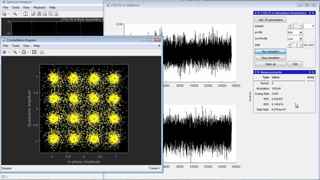
    • Simulating the throughput of a link-level scenario
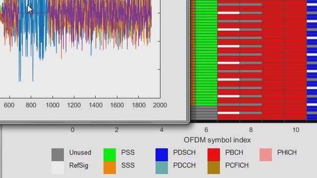
    • Recovering and decoding signal information and system parameters from synthesized or live-capture data
    • Analyzing the impact of RF components or interference signals on test measurements (EVM and ACLR)
    • Generating and working with NB-IoT waveforms

    Published: 4 Mar 2021

    Hello. My name is Marc Barberis. I'm part of the Application Engineering Group at MathWorks. Welcome to the LTE presentation. We'll look at how to generate and analyze LTE and NB-IoT waveforms with LTE Toolbox.

    Our agenda today is as follows. I will start with a brief overview of LTE Toolbox. Then we will generate LTE waveforms, perform throughput measurement on scenarios, such as closed loop spatial multiplexing, demodulate an actual LTE signal captured in the field, and look at EVM and ACLR measurements in the presence of RF impairments. Finally, we will have a look at NB-IoT and how it differs from LTE and how to model it with LTE Toolbox.

    Let's start with a quick introduction to LTE Toolbox. LTE Toolbox includes over 250 functions for physical layer modeling. And it covers FDD and TDD, uplink and downlink, transmitter and receiver, as well as propagation channels. In terms of standard, LTE Toolbox encompasses all versions of the LTE standard, including LTE Advanced Pro through release 15.

    How do we see LTE Toolbox being used today at companies around the globe? The first and most frequent use case is to generate standard compliant LTE waveforms. With LTE Toolbox you can easily generate and customize LTE waveforms.

    The second one is modeling a complete end-to-end link level simulation. If your goal is to investigate the performance of an alert system under various conditions, transmission modes, and SNRs and measure the throughput of block error rate, you can take advantage of conformance tests that are included in LTE Toolbox and already set up, including a complete receiver and HARQ.

    The third case is to perform measurements, such as EVM or ACLR on LTE signals after they have undergone RF impairments or gone through a piece of hardware, and finally, signal information recovery. You're capturing some live signals from an NOB or a UE. You want to feed it into MATLAB and extract some information from that signal. It could be the set ID or mass information log or system information.

    In each case, it is useful to keep in mind that you can connect your MATLAB session to the real world. You can export and import real world data through an instrument with Instrument Control Toolbox or an SDR board, such as Zynq, Pluto, or Ettus boards by downloading a support package for the board.

    Let's now have a look at waveform generation. Let's start with an example that shows a generation of downing reference measurement channels, or RMCs. These are waveforms specified in the standard which we can generate with just a few mouse clicks, so let me switch to MATLAB.

    Let's start the wireless waveform generator app. You will find it in the App tabs under Signal Processing and Communication. The wireless waveform generator supports generic waveforms, as well as 5G NR, LTE, wireless Lan, and Bluetooth. Let's select a downlink RNC, or reference measurement channel.

    The standard defines those RMCs in order to let people compare the performance of the LTE system against a given benchmark. The wireless waveform generator app makes dozens of those available at your fingertip. R105 is a recent addition to this list with 1,024 QAM. It is a 20 megahertz or 100 resource block waveform with two antennas, as you can see here.

    You can also configure many other parameters, such as the set ID from this menu. When I select Generate, I get an LTE compliant waveform. It is all generated for you without having to know much about at LTE all. The top plot shows the spectrum of the generated waveform. And we can see it is 18 megahertz wide. The bottom plot presents a view of the OFDM grid, which is the grid before FDM modulation.

    The x x-axis is OFDM symbol number, which relates to time, while the y-axis is the subcarrier number or frequency. Most of the resources are assigned to the PDSCH, or data channel, in green. At this point you have several options. You can export the generated waveform to the MATLAB workspace or to a file. You can automatically generate MATLAB code that generates the waveform and visualizations.

    Or you can send this waveform to a connected instrument using the Transmitter tab. In this case, the app your network for available instruments, and you can set the carrier frequency and output power before hitting the Transmit button to have the waveform sent out over the air, if you have an instrument connected, which I don't have. Here we want to generate MATLAB code that generates this waveform.

    As you can see, we first retrieve all parameters associated with R105. We then define a payload and have a one-line LTE transmitter on this line. LTE RMCDL tool performs all the processing in an LTE transmitter and produces the output waveform, the OFDM grid, and the configuration.

    Here, I want to emphasize a really important point. You can change any of these parameters as to LTE RMCDL tool, and thereby customize the waveform by varying the modulation scheme, coding rate, resource allocation, transmission mode, and so forth.

    So this is a very quick illustrative example that accesses some of the functions in the toolbox. I'm not going into a lot of detail right now. But hopefully this gives a good idea of waveform generation with a toolbox.

    Let me summarize what we have seen so far. We can generate off-the-shelf waveforms, such as the RMCs, FRCs, and test models, from the Wireless Waveform Generator app. We can also generate the equivalent MATLAB code, and as I have just alluded to, you can modify any of those parameters to create your own custom waveform. And this is something we will see in upcoming examples.

    Before closing this first part of this presentation, I want to talk about carrier aggregation. LTE Toolbox also includes a carrier aggregation example, which we're all going to look at briefly. How are we going to find it? This is my chance to introduce LTE Toolbox documentation.

    When you start the documentation and click on LTE Toolbox, you'll see a section called Examples, as you would expect. LTE Toolbox ships with dozens of examples that cover waveform generation, throughput measurement, EVM and ACLR analysis, and so forth.

    If I look for aggregation, it points me to this example here. Let me run it, and we will see that we have aggregated one 10 megahertz, one 115 megahertz, and 120 megahertz carrier components. On the receive side, we use a sharp filter to extract the first carrier component and perform measurements on it.

    This window shows the EVM measured per symbol and per resource block. This gives us a little foretaste of what is to come in the measurement section. But what I want to highlight is how we generated those components. For each carrier, we started with appropriate starting points of the right bandwidth.

    Then in the loop, we can see how we generate each waveform with one single line of MATLAB, then bring all of them to a common sampling frequency and shift them in frequency before aggregating all of them.

    Let me get back to my slides here to summarize what we have seen so far. We've seen that you can trivially generate standard waveforms, such as RMCs, FRCs, and ATMs, but also full custom dynamic waveforms for your specific requirements.

    These capabilities are available for both uplink and downlink. And you can also aggregate carrier components. One very important point that we have not yet seen is that LTE toolbox that you configure several UEs and several eNodeBs without any additional effort. We'll see such examples in our next section.

    And our next section is about throughput measurement, which typically involves a transmitter, propagation channel, and receiver. LTE Toolbox includes many LTE specific propagation channels, such as the multipath fading channel. This channel includes typical urban, pedestrian, and vehicular models.

    Also included are the moving and high speed train channel models. All those channels are 3-D channel models, some of which have been around in a similar form since the GSM days. The last channel model mentioned on this slide is the 3-D MIMO fading channel.

    As its name suggests, the specificity of this channel is that it models rays in space departing and arriving at given angles. This is a great channel to investigate space beamforming. You can visualize those rays are represented at the bottom of this slide.

    In addition to these channel models, you can find a host of other channel models that cover other aspects of propagation, such as freespace loss or attenuation due to gas, fog, or in clouds. One recent addition to this collection is a retracing channel, another 3D channel model which lets you derive and model propagation between a transmitter and a receiver placed at specific locations within the city using up to two reflections off the walls and ground.

    The last arrow in your quiver before tackling a complete end-to-end simulation is modeling other impairments, such as phase and frequency offset, phase noise, and non-linearities. You will find that Communications Toolbox offers many of these impairments. You can parameterize them as needed to reflect a particular phase noise or non-linear model.

    At this point, we are ready to look at a complete end-to-end simulation. There are many such examples in LTE Toolbox, including PDSCH or data app report. What you typically have is a transmitter, channel, impairments, and a receiver, and closed loop information that controls possible re-transmission and dynamic informing.

    I want to highlight two such examples in the toolbox, one for code word base pre-coding schemes, such as transmission mode 4, and one for non-codebook-based pre-coding schemes, such as transmission mode 9. When running this example, you can obtain throughput plots such as the one shown on the right as a function of the SNR.

    Let us have a look at one of these examples. This is the list of LTE examples, and I select the end-to-end category. There's two examples here, the ones I was just mentioning. Let's look at the non-codebook-based pre-coding scheme example, which enables transmissions of up to eight layers. It supports transmission modes 7, 8, 9, and 10.

    Note how we set up parameters depending on the selected mode. Here are the parameters for the propagation channel, which is the pedestrian channel. And there are to loops, one to iterate on the SNR, and want to run a certain number of frames. At the heart of a simulation, after part dealing with HARQ, you will recognized the one-line transmitter followed by the fading channel and additional noise.

    We then enter the receiver per stay with timing estimation, de-modulation, channel estimation, MIMO EQUALIZATION inside the LTE PDSCH code function, and Turbo coding. At this point, we can compute throughput and bit error rate.

    One point that I want to emphasize is that LTE toolboxes is structured such that you can easily look at and replace functions with your own versions. If, for example, you have a more advanced equalizer, or a different way to compute something, you can simply swap out one of our function calls for your own IP, while taking advantage of the whole infrastructure to run performance simulations.

    What about the uplink? LTE Toolbox includes numerous end-to-end simulation examples for the uplink as well. The one shown here features two UEs simultaneously sending information using the control channel or PUCCH back to the eNodeB. The added difficulty here is that they are both using the same resource blocks in the opening grid, so they are taking advantage of orthogonal schemes on the resource blocks and the eNodeB can separate them.

    The next example includes several base stations. This example would deserve a whole presentation on its own, as it features a rather advanced capability called Coordinated MultiPoint, or CoMP.

    What we investigate here is a scheme called dynamic point selection, where based on the UE feedback, the network decides on the subframe by subframe basis, which base stations shall transmit data to the UE. This scheme is particularly interesting when a UE is hovering at the limit between two cells and the most suitable cell may change back and forth.

    Another question I get quite often is, can we model multiuser MIMO schemes and user-specific beamforming, which takes advantage of spatial separation? This example here visualizes such a configuration with one base station simultaneously transmitting to several UEs. This is based on TTD, where downlink and uplink transmissions share the same propagation channel.

    Precoding for each UE on the downlink is based on channel estimation performed on the uplink using the sending reference signals or SRS. Further optimization is performed in the base station to orthogonalize precoding for all UEs, since the transmission to one UE sends as little energy as possible towards any other UE.

    In summary, we saw that LTE Toolbox lets you assess block error rate, throughput, channel quality, but also RSSI on complex scenarios involving closed loop feedback and multiple UEs and eNodeBs, both for uplink and downlink. It supports multiple UEs, multiple eNodeBs, and massive MIMO schemes. In addition, the structure of LTE Toolbox that you easily swap modules, such as receiver algorithms for your own if you wish to.

    So far, we have focused on simulations where we generated the waveform ourselves. Here I want to show examples that ship with LTE Toolbox that can handle any LTE waveform that you may have. It may have been generated LTE Toolbox or just captured in the field or at an antenna connector.

    The first example is an LTE scanner. The scanner can grab data from a board that is connected to your computer, such as Pluto, Ettus board, BEN or X series, or Zynq SoC. It automatically scans the frequency bands selected for any LTE signal and reports the signal strength and set ID for each one of them. Again, let me emphasize that this example works on actual LTE waveforms captured of the air.

    Another example that processes externally acquired signals is the Cell Search, MiB and SIB1 recovery example. This is an exciting piece of code because it successfully syncs up to and de-modultates pretty much any downlink LTE waveform you can capture, provided it's long enough and has a reasonable SNR. Let's look at it in MATLAB.

    I find it under signal reception and recovery. Let me open it and run it. It performs cell search, including carrier offset estimation and compensation, synchronization and set ID detection. Then extracts and demodulates the broadcast channel, which carries the master information block, blindly looks for control information associated with system information block one or SIB one, decodes it, and demodulates and decodes the SIB1. Let's look at the log.

    The first step is to perform cell search. This is when based on the primary and secondary synchronization sequences, we figure out the timing and the set ID. So here we identify the set ID to be 17. Now that we have the timing, we can perform demodulation of the middle 72 carriers and extract the MIB. So we estimate the channel and decode the MIB, or Master Information Block.

    This gives us the number of resource blocks, which is 50 here, meaning we have a 10 megahertz signal. So now we know the cell bandwidth, and we can move to demodulate other channels.

    You can decode CFI information, get the information about the number of control symbols, then you can do a PDCCH search, decode control information, extract the system information block, and decode it. All of that is available in the MATLAB code.

    What good is that? Hopefully it is quite obvious, but let me state it nonetheless. With LTE Toolbox, you have the ability to extract information from an LTE signal with off-the-shelf demodulation capability. And you can further tailor and enhance this example for your specific needs.

    The third question is, how do you obtain LTE signals? You can take advantage of MATLAB's link to tests and measurements instruments to generate and capture off the air signals.

    This slide shows how Instrument Control Toolbox lets you automatically transmit an LTE waveform generated with LTE Toolbox in MATLAB by connecting MATLAB to Waveform Generator. And conversely, you can use Instrument Control Toolbox to automatically grab off the air of the data and feed it to MATLAB for further processing with LTE toolbox.

    Finally, another popular way to get signals into and out of MATLAB is to use hardware connectivity with SDRs, such as Zynq and Pluto. This capability is part of Communications Toolbox. We have demonstrated in our lab the ability to send and receive an LTE modulated waveform over the air using this type of connectivity.

    In summary, LTE Toolbox offers off-the-shelf demodulation capability of actual LTE signals. You can transmit and acquire LTE signals by connecting to instruments with Instrument Control Toolbox while taking advantage of SDRs.

    In this next section, I want to address EVM and ACLR measurements, along with the need to model RF impairments. EVM and ACLR are two fundamental characteristics of an LTE signal. Here are a few typical scenarios where you want to measure the EVM.

    You generate an LTE waveform and feed it to a piece of equipment or hardware that distorts it. It could be an amplifier or a receiver front amp. Or you may want to investigate the effect of RF impairments ahead of time using a model of the RF section.

    You will find several examples in LTE Toolbox that show EVM and ACLR measurements. We briefly looked at one of them, the carrier aggregation example, in our waveform generation section. You can introduce RF impairments, such as phase noise or nonlinearities, using available MATLAB models, which were reviewed in our throughput measurement section.

    This shipping example shows how to model detail of a superheterodyne transmitter structure using RF Blockset. Here we generate an LTE waveform with LTE toolbox in MATLAB and pass it to the RF Blockset Simulator, which works with Simulink. The RF Blockset the environment lets you model detailed RF components, such as non-linear amplifiers with memory, mixers, filters, and passive components using S parameters, and nonlinear characteristics.

    The resulting signal is passed back to MATLAB, where LTE Toolbox performs EVM measurement on the 1024 QAM consulation. With this environment, you can directly assess the impact of RF components on the signal quality.

    Let us look at our simulation set up. For the source, we selected Test Model 3.1B, 4,024 QAM. And we specify the bandwidth and duplex mode. This is the model of the transmitter in RF Blockset. If we look inside, you can see that this model includes an IQ modulator, an analog filter, a variable gain amplifier, and a high power amplifier.

    You can enter detail specifications from data sheets for each one of these components in this dialogue. Let me run this model we can see the spectrum of a signal at the output of a transmitter, the QAM 1,024 constellation. And the EVM is represented here with a 3D figure, EVM versus time and frequency subcarrier, with the other three plots showing the same data averaged over time or frequency.

    The final EVM measurement for the signal is around 1.4%. What is different about this example compared to all the examples we have seen so far is that it makes use of RF Blockset set inside of Simulink to incorporate a detailed model of the RF part. LTE waveform generation and analysis uses LTE Toolbox and associated MATLAB code.

    In summary, LTE Toolbox provides a great environment for EVM and ACLR measurement. You can use signals that were generated with LTE toolbox, signals you captured from a piece of equipment or hardware, or simulate and predict the effect of RF requirements using RF Blockset.

    In this final section, I want to briefly introduce what LTE toolbox offers for NB-IoT modeling. First, let's have a quick look at why NB-IoT was introduced and its main characteristics. As a quick reminder, NB-IoT was added to 3G PPLT with release 13, a significantly extended release 14. The main goals of introducing an NB-IoT option are to enable load data race, cheaper devices with long battery life.

    To that end, several simplifications and techniques have been incorporated, ranging from a low bandwidth of one resource block, 180 kilohertz, to a single antenna, reduce transmit power, and extend the sleep time. There are three types of NB-IoT deployments, stand alone in an unused part of the spectrum or within an LTE band, either within the LTE signal or in the guard band.

    NB-IoT uses the same OFDM grid as LTE, but with only one resource block. The grid being so narrow, each subframe only carries one type of channel, broadcast, or synchronization, or control, or data. That is a major difference with traditional LTE.

    You can see the time pattern on this picture. The broadcast channel is transmitted in all subframe 0, the PSS in all subframe 5, the VSSS in every other subframe 9, and the rest being available for data or control.

    The narrow band downlink share channel uses QPSK modulation and occupies one complete resource block. One important characteristic of NPDSCH is the possibility to have repetition up to 2,048 times, in order to provide extended range at low transmit power.

    On the uplink, both BPSK and QPSK are possible. In transmission may occupy as little as a single cell carrier. Subcarrier spacing of 3.75 kilohertz is also possible, In addition to the regular 15 kilohertz one.

    LTE Toolbox offers extensive support for NB-IoT, starting with uplink and downlink waveform generation. Let's have a quick look at a simple example for downlink. Here we declare a basic NB-IoT set up. We can generate the waveform and visualize it and the corresponding resource grid. You can see the different channels generated on the downlink, as well as the corresponding time signal.

    You can generate different scenarios. Let's change the deployment mode to in band and the number of repetition from 1 to 8. The top is the previous grid for standalone with no repetition. And the bottom is the new grid with PDSCH repetition in yellow and for in band. You can see that all channels now avoid the first symbols of each subframe, as those are used for the control region of the LTE waveform.

    As part of LTE Toolbox, you'll find examples for uplink and downlink waveform generation and throughput measurement. Modeling includes data control, broadcast synchronization in SIB1, as well as DMRS.

    Also part of a shipping examples is signal recovery example, similar to the one for LTE, which performs initial synchronization and MIB decoding. Let me finally mention that PRACH modeling was added to LTE toolbox in r2020b, compliant with release 15 features of the 3G PP standard.

    This brings me to my conclusion. I hope I've been able to bring to the floor some of the main benefits of LTE Toolbox. First LTE Toolbox is the comprehensive set of physical labor models and example. It is an open environment, not just because it is MATLAB based, but because you can link it to test and measurement instruments and RF simulation.

    Finally, this is a versatile product that appeals to LTE novices and experts alike because of the different levels of modeling, including the toolbox. This concludes my presentation. To learn more, please have a look at the LTE page and the wireless communications page shown on this slide.