Modeling a PEM Fuel Cell
Model a proton exchange membrane (PEM) fuel cell with a custom Simscape™ block. The PEM fuel cell generates electrical power by consuming hydrogen and oxygen and producing water vapor. The custom block represents the membrane electrode assembly (MEA) and is connected to two separate moist air networks: one for the anode gas flow and one for the cathode gas flow.
The two moist air networks represent different gas mixtures. The anode network consists of nitrogen (N2), water vapor (H2O), and hydrogen (H2), representing the fuel. The hydrogen, stored in a fuel tank, is supplied through a pressure-reducing valve to the fuel cell stack. Unconsumed hydrogen is recirculated back to the stack. The cathode network consists of nitrogen (N2), water vapor (H2O), and oxygen (O2), representing air from the environment. A compressor brings air to the fuel cell stack at a controlled rate to ensure that the fuel cell is not starved of oxygen. A back pressure relief valve maintains pressure in the stack and vents the exhaust to the environment.
The temperature and relative humidity in the fuel cell stack is maintained at an optimal level to ensure efficient operation under various loading conditions. The cooling system circulates coolant between the cells to absorb heat and rejects it to the environment via the radiator. The humidifiers saturate the gas with water vapor to keep the membrane hydrated and minimize electrical resistance.
Gernot Schraberger is principal application engineer in the Munich office of MathWorks with 14 years of experience in that position. His main application focus is on electrification, physical system modeling, and control design. Prior to joining MathWorks, Gernot worked as a development engineer for motor control and embedded software engineering in the semiconductor manufacturing industry. Gernot holds a master’s degree in automation engineering from the Technical University of Munich.
Published: 15 Jul 2022
I want to talk, now, about the multispecies fuel-cell modeling, including nitrogen diffusion and purging.
So how does a fuel cell work? We have hydrogen here, at the top, coming in at the anode. It's oxidized here, in the anode. That means it will lose the electrons. They are passing over the wire here, over the load. The hydrogen protons will pass the membrane.
And on the cathode side, we have oxygen here, coming in. It will be reduced, so that means it will take electrons coming over the wire, and together with hydrogen protons, it will be converted to water vapor here, which is exhausted. We have to focus on anode, cathode on this process here in the membrane, but we also have to think about the temperature and heat flows in the system.
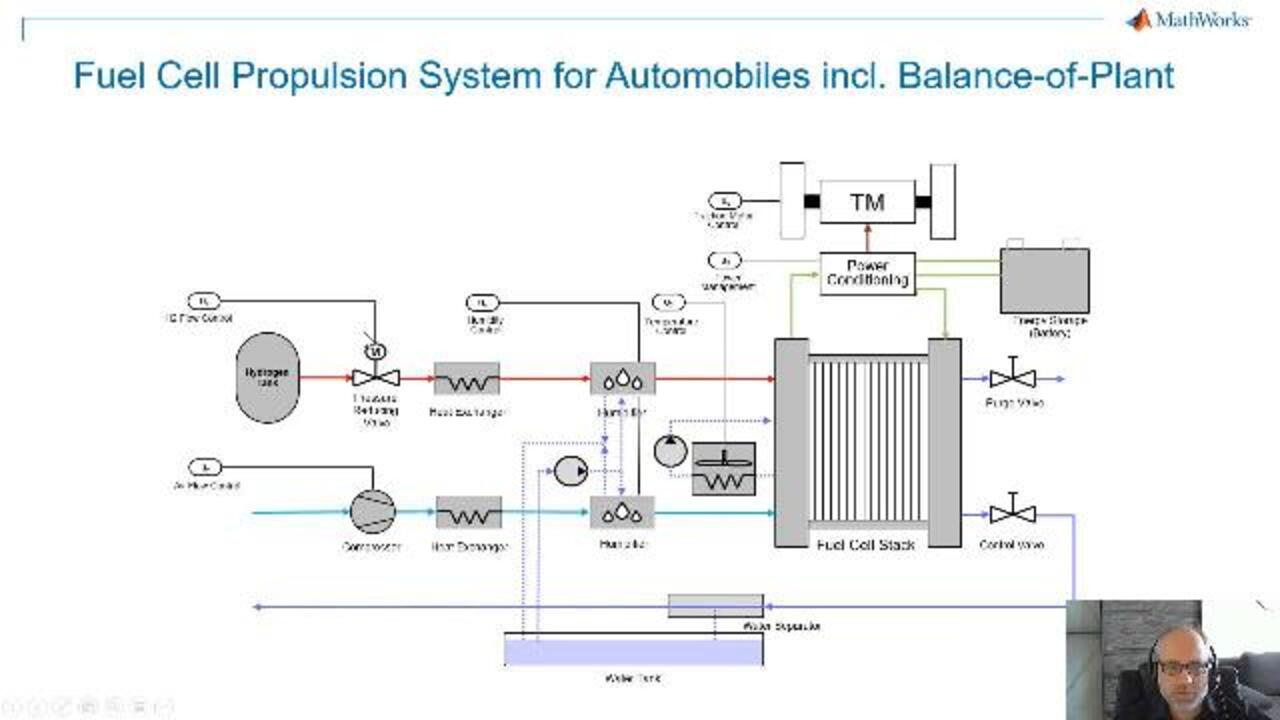
Well, let's have a look how such a whole system looks like. And that's a fuel-cell system, including the balance of plant. These are all these additional components around the fuel-cell stack. So here is the stack. And then, we have, for example, a hydrogen tank here. We have valves to reduce the pressure. We will have heat exchangers.
We have a pump here for the airflow. So, especially for the oxygen path, we have to have humidifiers because the membrane has to be operated with about 100% relative humidity. It should never get dry, because that will cause trouble.
Then, we also have to consider the load. This can be a power converter for driving an electric motor here. There also is a battery system which can be a backup for the fuel cell.
Here you can see the model. If we go through the single components now-- well, we start here with the hydrogen. We have got the hydrogen source, which is mainly a tank. And the tank in the model will be constant volume chamber.
We have a parameter list here. And you will see here, if you go into detail, that all the four species that we are focusing on have to be covered. So that means we use, typically, tables for the parameterization if they are depending on, for example, one other entity, like the temperature. Or we might use even more tables, like 3D tables, if we also have to make it depending on the pressure.
So indeed, we have four species here. We have a thermal connection port to the environment. In this case, it's isolated. We have a port where this tank is connected to the next unit, which is a pressure-reducing valve. And there are also some inputs where we can apply an external mass flow for these four species from outside with a specific temperature.
And we've got, also, some measurement connections here, measurement outputs for the mole fraction for temperature, for the pressure here. I explain it in that detail because you will see this concept all over the model, independently if it's a tank or any other volume chamber or a pipe element.
So what's done in this block is that we have to reduce this high pressure of the tank of about 700 bars to a pressure of about 1.6 bar for real operation. So we have got this pressure-reducing valve with some controller, and we have got a pipe element. Once again, as mentioned before, the same connection inputs for the mass flow for species and the temperature.
If you continue, the next partial system is a recirculation system because we come in here with hydrogen, but typically, not all the hydrogen is used on the anode side. Some part will be passing the anode, and it can be reused, so we have this recirculation to increase the efficiency. What you see in here is another volume chamber, in this case with three port connections. And then, we model an ejector in case of a controlled mass flow. And this mass flow is then controlled by the amount of current that is used on the electrical side.
Then, the hydrogen has to be wet, so we need 100% relative humidity so to be able to apply the hydrogen to the anode or to the membrane. So that's the task of the next controller here, where we have one that's 100% relative humidity. We measure the humidity, and we apply additional water. At the same time, we have to apply a temperature of the stack so that we can tell the system which temperature the water or water steam is coming in here.
Next part is the anode, a constant-volume chamber with several connections. We come in here at port C, we get out at port B, and we have a connection here to the membrane. This one is just used for getting temperature and pressure. There is no flow going over the membrane. The flow is controlled from the equations in the membrane by these external mass flows' inputs here.
We have got, also, thermal connection here, an exchange of heat with the environment. And we have an output used for the mass fraction of every single species. If we come back with the hydrogen on this path in the recirculation, we might also take some nitrogen from the membrane because we do not have ideal conditions in the membrane. And real membrane will also pass some water and nitrogen, and that will find in this path.
And now the point is, if the nitrogen level is too high, we cannot use this in the supply of hydrogen. We have to get rid of that. And that's the reason why we need an anode exhaust here.
The concept is that we measure the molar fraction of the nitrogen. That's the first component here of the four species. And we have a relay switch. And if we reach more than 50% of the molar fraction, we have to purge the gas combination, and we have to restart the process. And the purging will happen as long as we're in the range between 0.5 and 0.1.
So I have started a simulation already before. That means I can use a specific representation of outputs. And that's within the same Simscape Results Explorer. We see, already, some concentrations here.
But if we look, for example, specifically to the end of the exhaust and we say, well, we are interested if the purging works correctly, then we can check. Well, we have got this connection, port A, off the end of the exhausts that we have. Port A. And you see, here, we can measure the molar fraction and the mass fraction.
So if we click on here, on the molar fraction, we see the first species, which is nitrogen. Nitrogen level is increasing here until we reach this level of 0.05. Then, we start the purging. We are going down to the level of 0.1. And these are exactly the values that we have specified. That's a way of checking if the behavior is correct.
We can see, in this path, which species can be found. So we can find, as seen here, the nitrogen. In orange, we have oxygen. That's 0. That means we have no oxygen on that side. That's the other side.
You can see, in yellow, hydrogen. You see the level is going down until we do the purging. Then, it's going up again. And we have to keep the level of this over a certain threshold.
Next thing is the membrane. The membrane is a custom component. We'll just show, later on, how you can use Simscape language to build such custom components.
Now, if we look to the right side, that's the oxygen path, and it is built up very similarly like the hydrogen path. The only big difference is that oxygen is coming from the environment. It has the ambient pressure about one bar, so we need a compressor here to increase the pressure. But we also have got controllers here, in a similar way, driven by the current demand from the electrical side.
We have humidifiers built up in the same way, cathode built up in the same way as on the anode side, and then the cathode exhaust. What else can I show you here in the model? One thing is the thermal connections here from the anode, cathode, and membrane. It's actually an interesting cooling system, possibly. Cooling system has got a pump, a cooling cycle with a heat exchanger modeled as a simple pipe on one side, and then a radiator on the other side to get rid of the heat. And we have got a thermal controller where we want to control the temperature at 80 centigrade.
Well, I already mentioned before that the membrane is modeled with Simscape language because it's a custom component. Well, the Simscape language is based on MATLAB language. And it will generate Simscape blocks, so you can add a mask. You can add images for better recognition of the block. And I use the local restrictions example, which is part of this custom domain for the fuel-cell modeling.
So if we look to the source code, a Simscape language file typically starts with the expression component to describe a component. But for the component, we'll have the component name next to the keyword component, local restriction, the input with the name AR. Then, we have the connection ports A and B. And next thing is the parameter mask. And you will find the prompt for the parameters here.
The most important part of Simscape language files are the equations. The equations are expressing the behavior of the component. And the equations, for examples, are equations concerning the pressure, concerning mass balance, energy balance, and a few other things.
Well, we started, now, with the most detailed way of modeling fuel-cell systems with a balance of plant. We can use that one for all the design for controller tuning, for figuring out concentrations of the gases within every specific branch. But for some other reasons, you might need simpler systems.
And, well, we also have got fuel-cell blocks in Simscape Electrical, like the simple fuel-cell block. There's another parameterization variant where we can set it to Detailed so it's a first-principles model, but without the gas dynamics. And there's something in between here as well. That's a lookup-table-based modeling approach with no dynamics, based on data.
Simscape offers components for fuel-cell modeling on various fidelity levels. Then, they've shown, here, the different domains used for fuel-cell modelings. And the last point is that fuel-cell modelings can be used for control design and algorithm development for integration studies and for system and control parameter optimization so you can fine-tune your system on the algorithmic side, but also on the physical side.
Learn More

Featured Product
MATLAB


Seleccione un país/idioma
Seleccione un país/idioma para obtener contenido traducido, si está disponible, y ver eventos y ofertas de productos y servicios locales. Según su ubicación geográfica, recomendamos que seleccione: United States.
También puede seleccionar uno de estos países/idiomas:
América
- América Latina (Español)
- Canada (English)
- United States (English)
Europa
- Belgium (English)
- Denmark (English)
- Deutschland (Deutsch)
- España (Español)
- Finland (English)
- France (Français)
- Ireland (English)
- Italia (Italiano)
- Luxembourg (English)
- Netherlands (English)
- Norway (English)
- Österreich (Deutsch)
- Portugal (English)
- Sweden (English)
- Switzerland
- United Kingdom (English)