Fuel Cell Electric Vehicle (FCEV) Architecture
Learn how Simulink®, Simscape™, and Powertrain Blockset™ are used to develop a fuel cell electric vehicle (FCEV) architecture. Modeling and simulation are used to demonstrate how the fuel cell interacts with aspects of an electric vehicle, such as:
- Drive cycles and operation scenarios
- Electric motor, DC-DC converter, battery system, and drivetrain
- Supervisory and feedback control algorithms
Other aspects of the fuel cell operation are also covered, including how to:
- Determine instantaneous power demand
- Convert power demand into current demand
- Distribute current demand between the battery and fuel cell
- Translate current command into hydrogen/air flow commands
Published: 22 Jun 2022
I'll start with a common challenge people see when working with modeling fuel cell electric powertrains. The challenge is that the fuel cell system doesn't live by itself, but instead interacts with the rest of the powertrain at all times. Different drive cycles or operation conditions puts different power requests and boundary conditions around the fuel cell system. The instantaneous state of the motor, the battery, the vehicle itself, and also the controllers can all affect how the fuel system works.
So one-- probably oversimplified-- example we have in the bottom right corner, regarding how the fuel cell system is operated inside a fuel cell electric vehicle-- the controller will determine the instantaneous power demand from the driver inputs, and convert that to current demand, and then decide how much current to draw from the battery versus how much to draw from the fuel cell. Then, the local controller, or the fuel cell system, will need to respond and translate that current command into how you handle the hydrogen and the airflow.
So all these are closely coupled in this fuel cell electric powertrain. Not only the external input change how the fuel cell system operates, but also the actual behavior of the fuel cell system itself can have an impact on the rest of the powertrain, as well. So we, therefore, aim to provide a modeling framework to enable the modeling of these interactions together, with different levels of details on the fuel cell system itself. So great.
So next I will switch to a a video. I will show you a video of this modeling framework in action. Here, we're looking at a virtual vehicle model, with a fuel cell powertrain, including the drive cycle, the driver controller, and the actual drive train. Inside this controller, we can locate the module that controls the fuel cell. And here we are comparing two cases.
The baseline is a fairly simple control logic. It's trying to maintain the battery state of charge around 60%, I believe, while keeping up with the power demand, using mainly the fuel cell. The other case-- we put a rate limiter on the fuel cell current command, so it becomes more gradual and we'll have the battery pick up more transient demand.
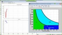
So we'll have the video keep going. So we'll compare these two cases. On the right, we'll see the current of the fuel cell on the top and current of the battery on the bottom. The orange line is the one we have a rate limit on the current for the fuel cell.
The current-- the orange line for the fuel cell part, it become less spiky, which means the current draw from the fuel cell become less-- change more gradually, which usually means a better efficiency for that because, typically, the fuel cell tends to run more efficiently in the lower current range.
Of course, to compensate for that, current from the battery become more spiky, which is usually well-handled by the batteries themselves. As a result of that-- it may not be obvious, on the top left plot, here, is the fuel economy-- actually we can gain about 1% increase in the fuel economy, by changing a small factor inside the controller.
The SOC of the battery was kept around 60% pretty well. We have a little bit more variance when you have the rate limiter on the fuel cell controller, because the response time will be slower. But that's OK. It's kept around 60% pretty well. So this is a simple example of a virtual fuel cell, electric vehicle build using MathWorks tools.
Next, I'll show you a little bit more about this framework, and then the model of the fuel cell system itself. I'll switch back to the slides. OK.
So here is the framework of modeling a virtual vehicle. The same framework, actually, applies to many different kind of vehicles-- battery EVs, hybrid EV, and of course, fuel cell EVs. And there are tools to help you to configure different powertrain configurations.
There is a demo showcase in the exhibition hall on this virtual vehicle framework. And there are multiple other reference applications. So go ahead and check it out.
This framework include profiles of different drive cycles, all the way on the left-- a longitudinal driver model, controllers for the powertrain, and the passenger car model that includes the physical model for the powertrain itself. This provide the environment to model different parts of the powertrain, study the sizing and the integration of different systems in the design controler algorithm, and calibrate and analyze the vehicle performance. Second, all these can be done while including all the interactions between each different subsystems and the controllers, and all doing these under realistic operation scenarios.
So inside the passenger vehicle model, we can include electrical plant filled with MathWorks physical modeling tools. In this application, we have included the fuel cell system itself, of course-- the motor, the battery, and the thermal management system. Inside the fuel cell and the battery, there are also boost converters to handle the balance of the load between these two sources of power. And that's what's enabling the control algorithm we tested in the video before.
So with this virtual vehicle model, we can study the fuel economy. You'll see this-- some of these figures before-- the performance, the thermal management on the full vehicle level. Here, we're showing a small set of the different things you can observe from this-- vehicle speed, current from the battery and the fuel cell, SOC, these, and the temperature in different parts of the vehicle. So that'll give you a framework to test, sort of, a real life behavior of these thermal management system and whether-- any interaction between the subsystems.