Modeling and Simulation of Faults in a Battery System
Overview
MathWorks engineers will demonstrate how to model and simulate faults in battery systems. We will showcase:
- How to inject faults in a battery model including additional resistance fault, internal short fault, and exothermic reactions.
- How to characterize the thermal runaway behavior of a battery cell by simulating an accelerating rate calorimetry (ARC) test.
- How the battery management system (BMS) responds under fault conditions.
- How to conduct a Failure Mode and Effects Analysis (FMEA) per industry safety standards while leveraging simulation results
Highlights
Attendees will learn how to:
- Inject and simulate faults in a battery model using Simscape Battery
- Characterize the thermal runaway behavior of a battery cell using Simscape Battery
- Detect fault conditions using Stateflow
- Conduct a Failure Mode and Effects Analysis (FMEA) of a battery management system (BMS) while leveraging simulation results using Simulink Fault Analyzer
About the Presenters
Danielle Chu is a product manager at MathWorks supporting the Simscape product family and specializing in power electronics and battery systems. Prior to joining MathWorks, Danielle was at John Deere for 7 years, involved in developing power electronics control systems. Prior to employment at John Deere, she performed postdoctoral work at the Center for Advanced Power Systems (CAPS), Florida State University and received her PhD in electrical engineering from the University of South Carolina and her MS in electrical engineering from Mississippi State University.
Pat Canny is a product manager at MathWorks supporting the Simulink Verification and Validation product family. Pat has a technical background in helicopter flight control systems and jet engine control systems.
Recorded: 28 Mar 2024
Hi, my name is Danielle Chu. I have been a product manager at MathWorks for two and a half years. Prior MathWorks, I worked at John Deere for seven years on power electronics control and control system integration, after a half year postdoc experience at the Florida State University. Now I work with our development team on products to help engineers to design battery systems.
I'm joined by my colleague Pat Canny, who will introduce himself later in the webinar. Today, Pat and I will explain how MathWorks tools can be used for modeling and simulation of force in a battery system.
Simulating force in battery systems early in the development process helps save time and effort, while increasing the safety compliance. Engineers spend time to ensure BMS robustness to different faults. Many potential issues are tested, including communication problems between the battery and the sensors, such as noise, signal drift, delays, and so on.
Engineers also test faults within the BMS and the battery, such as open circuits and short circuits. Simscape battery enables the simulation of complex faults, including cell thermal runaway, disconnection, defective wires, and manufacturing induced cell abnormalities.
We can use fault injection as a tool to identify failure modes when we are running failure mode and effects analysis, FMEA, or functional hazard assessments. We can use fault injection desktop simulations to get requirements on battery system components, like what's the minimal thermal conductivity and thickness required on the thermal interface material to stop thermal runaway.
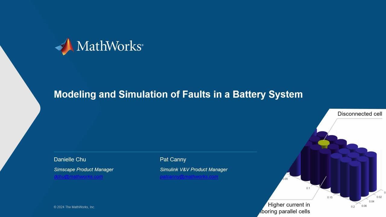
We can also perform a tolerance study. What happens if certain cells are disconnected in the battery pack? How does the battery pack perform under such condition?
This example shows a disconnected cell in a 9p3s battery model. The disconnected cell fault triggered a 30 seconds of simulation. This disconnection can be external, like for a defective wire bond, or may be even inside the battery cell. Looking at the plot on the right, when the cell becomes disconnected, all the neighboring cells immediately experience an increased current load, up to about 50 amps.
The plot on the middle shows the parallel assembly voltage, measured by the BMS, suddenly drops due to the increased load on the remaining cell. The plot on the left shows the neighboring cell temperature begin to rise, due to the added heat generation.
At the end of the webinar, you will learn three things. First, you will learn how to inject and simulate three different types of faults at the cell level in a battery model. Additional resistance fault, internal short circuit fault, and exothermic reactions.
Second, you will learn how to characterize the cell thermal runaway using a simple first order kinetic model. Then you will learn how to add these faults for a larger battery system, like a battery model. Last but not least, you will learn how to conduct fault analysis of a battery management system in a systematic way.
First, let's start with the battery cell level for the simulation. You can add a non-intrusive force by programming additional equations within a Simscape block that will be used whenever a fault is triggered during simulation. An example is the battery equivalent circuit block in Simscape battery. This battery equivalent circuit block represents a single battery cell.
In normal operation, this block models the electron thermodynamics of battery cell by using equivalent circuit model and a zero dimensional lumped mass thermal liquidity equation. Whenever a fault is triggered, the equations that describe the normal operation of the block will be augmented with new equations that describe the fault behavior.
We have added support for three different types of fault and these fault can be injected at specific time when a certain condition is fulfilled. Additional resistance fault. If this is triggered, a resistor will be added and connected in series internally. This is similar to an open circuit fault, which can be used to simulate internal or external cell disconnection, such as missing tabs or wire bonds, manufacturing defects, and so on.
Internal short fault. If this is triggered, a resistor will be added and connected in parallel with the battery cell. When the resistance value is low enough, this can be used to simulate an internal short scenario. As mentioned earlier, these are non-intrusive faults, so you don't need to connect a resistor to the battery cell. The fault model itself is a separate model file.
Exothermic reactions even enable you to simulate a thermal runaway event by capturing the heat generation and the cell mass reduction. You can edit the the fault behavior by modifying the fault parameters in the fault model.
For example, the resistance value in the additional resistant fault, and the internal short fault were the parameters to calculate the released heat rate in exothermic reactions. The Simscape source code is open, so you can open up and see how these faults are implemented. You can also add customized faults into the cell model by modifying the source code of the battery equivalent circuit library block.
In this case, we are simulating a single battery cell connected to a constant power load, and the cell block contains a simple thermal model and a thermal path to ambient. When you click on the battery equivalent circuit block in the Simulink canvas, you will see a new tab option at the top of the model called Simscape block. This tab contains relevant options to fault injection, like the option to visualize the fault table.
You can manage all your faults and fault table. As you can see, we have added all the three types of faults. The additional resistance fault is triggered at 50 seconds. Let's look at the results.
As expected, both the current and the voltage went to zero when the fault was triggered, which mimics an open circuit of the battery. The battery state of charge stay the same, and the temperature gradually decrease due to the ambient thermal path.
In this case, we are simulating the same model as before. We inject an internal short circuit fault, which is modeled as a parallel connected resistance. The short circuit fault is triggered at 50 seconds. As expected, the current spiked from 3 amps to up to more than 400 amps.
The final current is determined by the parallel resistance value and the cell characteristics. The terminal voltage of the battery immediately went to zero. In addition, the temperature started to increase rapidly, and the battery state of charge was quickly drained down to almost zero. Realistically, most kinds of lithium cells would probably go into thermal runaway above 80 to 100 degree Celsius, what would event triggering a cell disconnect. But this simulation does not include that behavior.
It's important to consider the limitations of the simulation and the physics that is actually programmed into the models. In this case, the simulation results would stop making sense a few seconds after the internal shortfall is triggered.
Next, we are going to talk about the exothermic reaction fault and how to characterize the battery cell thermal runaway. The battery cell thermal runaway is typically characterized by using accelerated rate calorimetry, or ARC test in a lab environment. The main goal of this test is to obtain the temperature of the battery over time, the total heat released in some advanced setups, the volume of gases generated, and their chemical composition.
In the ARC test, a battery cell is gradually heated following a heat-wait-seek procedure until a certain self-heating rate is reached. Once this point is reached, a cascade of self-sustaining chemical reactions start to occur inside the battery, which gradually cause higher rates of heat generation, rapid change, and degradation in the cell materials, and rapid temperature increase to hundreds of degrees Celsius.
In general, the rate of temperature increase depends on the initial SoC. And therefore, the ARC test is often repeated as several initial SoCs. For an ARC test, we would typically obtain the total heat of reaction, the temperature over time, and the rate of change of temperature at each temperature point.
With the Simscape Battery, you can directly load these output vectors into the exothermic reaction fault model. Here, we have selected the tabulated ARC test temperature rate, which exposes these parameters at the block mask level.
This is the fault behavior configuration window. You choose the fault modeling fidelity as a tabulated accelerated rate, a calorimetry test or temperature rate. And input the total heat of reaction act as a temperature vector, and the corresponding ARC test temperature rate.
Given the high dependency of heat generation and reaction rates with SoC, we also provide the option of adding multiple ARC profiles for each SoC. Now we will showcase the exothermic reaction or thermal runaway fault. In this case, we are simulating a single battery cell connected to a constant power load, and the same thermal settings as before.
You can see in the fault table that both the internal short circuit fault and the exothermic reaction fault have been enabled as part of the simulation. The short circuit will be triggered at 50 seconds of simulation time, causing battery temperature to increase and leading to a thermal runaway.
As expected, the moment the short circuit occurs, there is an immediate surge in current, instantly exceeding 400 amps, causing the cell terminal voltage to quickly drop. As previously mentioned, the current is determined by the resistance value of the parallel resistor, introduced by the fault. The resistance value depends on many factors, like the specific initiation method, if it's a internal or external short. Following the short circuit, the temperature will rise exponentially, eventually causing the cell temperature to surpass the thermal runaway threshold.
As a result, the cell will enter thermal runaway, causing the temperature to rise even further. During the thermal runaway, the cell is disconnected due to damage to its internals, which could also lead to venting, and potentially a fire. The simulation also outputs the state of charge variable, but this value loses much of its significance shortly after the short circuit is triggered.
The battery equivalent circuit block in Simscape Battery provides two options for inputting parameters for a thermal runaway model. We have already seen the option which directly utilizes the tabulated ARC test results. Another option to input the parameters is the analytical option, shown here in the fault properties mask.
This option assumes that the heat generation is a function of the measured cell temperature and the extent of reaction, which goes from zero, meaning the start of the reaction, to one, meaning to the end of the reaction.
The heat rate function is represented by a typical chemical reaction rate kinetic expression. This option requires pre-fitted parameters to run, which you can obtain or tune from your ARC test data.
In addition, this option might be more convenient to just quickly try different parameter values from literature, or from assumptions to match a desired ARC profile. Like the tabulated one, the analytical modeling fidelity have the SoC dependence too.
We just finished the fourth simulation on cell level. Let's talk about simulating faults in a battery model. In this video, we show the complete workflow for creating a fault injection simulation at a battery model level. First, using Battery Builder app in Simscape Battery, we can define the battery model design and layout, including the number of cells electrically connected in parallel and the number of cells electrically connected in series.
Once we have defined the battery model design, we can automatically generate a Simscape library block over the battery model with only one click. Second, we create a Simulink model with the newly created battery model and enter the required faults. We can click on the model mask and enter the required fault type for any battery cell model block contained inside the model, which in this case, is the additional resistance fault.
In this example, we are interested in understanding the effect of one specific disconnected cell. We will define cell number 5 in parallel assembly number 2. Afterwards, we can define the value of the electrical resistance to a very high value, to simulate a cell disconnection or open circuit.
Finally, we run the simulation. In this simulation, a disconnected cell fault is triggered at 30 seconds. The cell disconnection affects the neighboring cells immediately by increasing the current. This increase in current immediately impacts the voltage of parallel assembly, or the super cells.
And this increase in current raises the temperature of the neighboring cells. Here, we are simulating the same 9p3s battery model. We have added a short circuit for trigger a 30 seconds of simulation.
In addition, we have enabled the exothermic reaction force on all cells, which provides the capability for each cell to enter thermal runaway once its temperature threshold is exceeded. This short circuit can be external, in the case of nail penetration, or maybe even inside the battery cell, due to the dendrite formation.
As we briefly show in the plot on the right, when the cell becomes shorted, all the neighboring cells suddenly come under very high current loads, higher than 400 amps. These are the two effects.
The first one is shown in the middle panel is that the faulty parallel assembly voltage, measured by the BMS, suddenly drops to zero. The second effect is that all the cells in the faulty parallel assembly suddenly goes into thermal runaway. The main effect of this short circuit is that the battery model becomes suddenly and permanently disabled.
So far, we went through fault simulations on cell level, characterizing battery cell thermal runaway, and battery model level fault simulation. Next, Pat will show how to conduct systematic fault analysis of a battery management system.
Thanks, Danielle. So Hi, everyone. My name is Pat Canny. I am a Product Manager in the Simulink Verification and Validation team here at MathWorks, and we support a lot of different areas around getting the design right before you generate code, and we're also supporting a lot more in the area of fault modeling, which we'll talk about more today.
So my talk will be about systematic fault analysis of a battery management system. And Danielle did some great work talking about injecting and simulating faults in a battery model and talking about thermal runaway characterization. But I'll be playing the role of a systems engineer, because I want to know if the overall system is robust against faults.
Now, this is very important for safety critical systems, and it's actually called out in certain standards, such as SAE J2929, which requires a completed and documented fault analysis, which shows that plausible single point faults will not result in fires, explosions, ruptures, or high voltage hazards.
As an electric vehicle owner, this is very important to me that we don't want to have anything happen, for instance, with our road vehicles with a lot of batteries in them. So what I'll do today is I'm going to just sort of jump in and show how you can use simulation and MATLAB and Simulink to start to ensure that your system is robust against these fault conditions.
So with that being said, I'm going to jump into MATLAB. So here we have a closed loop model, which includes a battery plant, which includes a lot of the components and blocks that Danielle walked through earlier. Has an EV battery pack with a bunch of-- with two module assemblies, and within each module assembly has four modules.
And in addition to that, as a Simulink guy, I always like to show the Simulink controls. We have a battery management system control. And here, we have a few key components that I want to talk about.
The first is, if there is a fault we need to be able to detect it. And that can be-- that's shown here in this fault monitoring subsystem. Now, there's three different categories of faults which are detected here. Battery current monitoring, battery voltage, and battery temperature monitoring, with a helpful little output of fault presence, which is just going to indicate to the rest of the controls that a fault has been detected.
Now, if a fault is detected, the supervisory control will mitigate that fault by changing the state of the system or the commanded state of the system. And this is modeled using a state flow state chart here in this supervisory logic state chart.
And basically, this is going to determine when the system should be either in idle, driving, or charging. And if a fault is present, it enters this fault state. It transitions to the fault state.
And so, again, the goal with my analysis is going to be, if a fault is injected-- a single point fault is injected in the system or is detected in the system, is it properly detected and properly mitigated? Is it going to actually, for instance, stop the charging if a fault is detected during charging?
So this system is actually a test harness. And one of the important things I also wanted to talk about was this test sequence block, which is going to drive the system. It's going to determine the inputs for this requested state of the system. The test sequence block is a feature in Simulink Test, which allows you to author test cases based on steps.
So this is a fairly simple one. It's just basically going to simulate a driving scenario. And it's going to drive the system from stand through standby, driving states, and charging states. I also included this little convenience. It is charging, which is a simple Boolean, which we use-- we'll show later with one of the faults we can trigger.
And this is going to kind of walk through this using simulation time. You don't have to use simulation time. It's just for demonstration purposes it's a little easier.
So about the first minute, we're going to be in the standby state. And then we're going to go into driving for a little while. And then we're going to start charging. And now we can inject faults at any point in time during the simulation, but we're going to be sort of driving this through these three steps.
Now, it's very important if you have a system like this where you're in multiple domains, that you understand where the different faults are in the system. Now, I could dive into the battery plant system, and I think there's something maybe in module assembly two, maybe module four. But I'm not sure.
But hey, right down here at the bottom we have the fault table, which is a feature in both Simscape, Simscape Electrical, Simscape Battery, and our new Simulink Fault Analyzer product, which allows you to know where and how faults can be injected in a model.
And basically, for demonstration purposes, I just have a few faults modeled in this model here. I can actually see where they are in the system. For instance, I have two faults associated with module assembly two in module four, in module assembly two.
And these are both additional resistance faults. One is going to be injected early on in the simulation in the standby phase. And one is going to be injected sometime during the charging phase of the simulation.
I also have another fault here, which is on a Simulink signal, which is-- I'll just show you where that is. I can also inject faults on the sensor values. For instance, the battery voltage sensor.
Let's say I want to have it set to ground, for instance, at some point during simulation. I can actually show you what that looks like. This is a separate model. And for more information, please feel free to consult the Simulink Fault Analyzer documentation. But this is what we call a fault model.
It's a separate model kept outside the model under test, or the model being simulated. And during simulation, when the fault is active and has been triggered, it'll inject a value back to the signal's value. It'll override the signal's value. In this case, it'll inject a ground fault here.
And I have this configured to be triggered as soon as the system has gone into charging. This is called a conditionally triggered fault. Again, feel free to consult our documentation for more information. But the way to think about this is instead of just a timed based fault, or a fault that's injected at the beginning of simulation, I can inject this based on a system condition of interest. In this case, when the system is just gone into charging.
So this is great. But how do I know if a fault, once I've injected, it has been properly detected and mitigated. Remember, that's my goal here. So I can do that by-- if I wanted to just, for instance, see one fault at a time, I can use the Simulation Data Inspector.
And in this case, I've already run the simulation. And I know that as soon as the system goes into charging, measured by this BMS state signal, it's gone from idle to driving. And as soon as it-- you can see that little line down there-- as soon as it goes into charging, the fault is triggered.
I can see the fault is triggered up here. Faults are automatically logged during simulation. And I know it's been detected here. So I know it's been triggered, it's been detected, and properly mitigated. That's great.
But how do I make this systematic? How do I do this systematically and make it repeatable? And don't forget, I have to document this if I want to be compliant with standards, such as SAE J2929.
So let's get organized. And we can do that using the Safety Analysis Manager, which is a feature in our Simulink Fault Analyzer product. Now just real quick, I'm going to explain what this feature does and why you should consider using it for fault analysis.
Now, the feature is designed to support and automate and improve analyses, specifically tabular analyses, such as fault analysis, as well as safety analysis, such as failure mode and effects analysis or FMEA.
But for today, I'm just going to start a fault analysis. And this is just a simple start to kind of get you started here. And what it's doing here is I can actually document the location of the fault. For instance, assembly two module four.
I can say, what type of fault it is. What's the behavior of this fault? For instance, I can do additional resistance or stuck at ground. I can document when it's injected, standby, or during charging. And this is just what we call a derived column, which is just concatenating these four columns here to have sort of a unique instance of a fault.
The other thing I can do is I can link from a cell to anything in the MATLAB ecosystem. This uses our traceability technology from our Requirements Toolbox product. I can link, for instance, the test cases, items in Simulink, requirements in within Simulink in Requirements Toolbox, as well as third party tools such as IBM Rational DOORS or DOORS Next Generation.
And then what you can do with that is you can see where this is actually going. For instance, I know this fault here has been linked from that cell. I can monitor-- I can also link to my detection logic here. So I know this fault should be detected by that, the battery current monitoring subsystem. And the mitigation logic is just the supervisory control system.
Again, you're leveraging traceability, and you can automate these workflows using the power of MATLAB, and validate the assumptions you're making here using simulation. And what I'll show you here is just how you can automate that through callbacks.
So every spreadsheet which can be authored and edited and analyzed in the Safety Analysis Manager has a set of callbacks. And the most important one that I always like to talk about is the Analyze Spreadsheet. So what happens when I click that button, is the Analyze function callback runs. And in this case, I have it running a live script from MATLAB, a MATLAB live script called Validate BMS Fault Analysis. And I'm just going to run this real quick and then tell you what it's doing while it's running.
So what it's doing is, for every row, it's determining whether the fault for that row has been properly detected and mitigated. In this case, I can annotate the table and say, yeah, this is actually correct, in that each fault was detected during simulation and it was properly mitigated. And I also updated the status of this validated cell. It's just a simple checkbox.
And I can actually export this to Excel for my documentation. So I've automated steps. I've leveraged traceability data. And I've been able to export it. And what actually happened is-- I can show you real quick what that script looks like.
This is just a bunch of MATLAB code that uses-- that leverages our APIs, our functions in Simulink Fault Analyzer. And it's loaded-- I already ran the simulation, so it loads those simulation results. It leverages some of the, again, some of the APIs and the traceability information from each cell. And it's actually going to just quickly go through for each cell and determine whether it was detected and mitigated. And then if that's the case, if it's both detected and mitigated, it updates the value of that validated cell, and for reporting purposes.
So just to summarize here. With Simscape, Simscape Battery, and Simscape Electrical, and Simulink Fault Analyzer, you can manage faults across multiple domains and then automate this and make it repeatable and systematic using the Safety Analysis Manager. So now I'm comfortable that things are working well and I can continue working on my fault analysis to try and be compliant with SAE J2929.
In addition to that, within Simulink Fault Analyzer there's other capabilities I just wanted to highlight. So I mentioned this new product, which is my product Simulink Fault Analyzer. And we focus the product in four different areas. And this is areas that you should be able to explore when conducting fault analysis.
The first is the ability to model faults without modifying the design. This is especially important with cases where you want to do scalable fault injection and really stress test your system, both in Simulink as well as other domains, such as Simscape, starting with Simscape Electrical and Simscape Battery, and more to come in coming releases. As well as our System Composer product for architectural analysis.
As I showed, you can also use the Simulation Data Inspector to simulate and explore faults and analyze their effects. And finally, you can be able to perform systematic safety and faults as you learn today analysis using simulation.
So what are the key takeaways from today? You learned a lot today from Danielle and me, and I just wanted to kind of highlight those key points. So Danielle showed you how to inject and simulate three types of faults in a battery model, such as additional resistance, internal short circuits, and exothermic reactions, as well as how to characterize a cell thermal runaway.
Then I jumped in and talked about systematic fault analysis of a battery management system. Remember, these are components that go in larger systems, and we have to ensure that those larger systems are robust against fault conditions.
Here's a set of additional resources you can consult. We have some great examples of battery fault simulation and fault analysis. Here are some also some links to the three products we highlighted. Simscape Battery, Simulink Fault Analyzer, and Stateflow, as well as two fantastic essential series for Simscape Battery and Simulink Fault Analyzer. I created the second one, but I think they're both awesome, and I actually stole a lot from the Simscape Battery team. The concepts are great.
With that, I just want to thank you for your time today. And always feel free to reach out and to learn more. And you know, go off and do great things with fault analysis.
Featured Product
Simscape Battery
Up Next:


Related Videos:


Seleccione un país/idioma
Seleccione un país/idioma para obtener contenido traducido, si está disponible, y ver eventos y ofertas de productos y servicios locales. Según su ubicación geográfica, recomendamos que seleccione: United States.
También puede seleccionar uno de estos países/idiomas:
América
- América Latina (Español)
- Canada (English)
- United States (English)
Europa
- Belgium (English)
- Denmark (English)
- Deutschland (Deutsch)
- España (Español)
- Finland (English)
- France (Français)
- Ireland (English)
- Italia (Italiano)
- Luxembourg (English)
- Netherlands (English)
- Norway (English)
- Österreich (Deutsch)
- Portugal (English)
- Sweden (English)
- Switzerland
- United Kingdom (English)