Generate MIMO OFDM Channel Realizations for AI-Based Systems
R2026bThis example shows how to generate channel estimates to train AI-based systems, such as an autoencoder for channel state information (CSI) feedback compression and temporal channel prediction. In this example, you:
Configure a carrier and a multiple-input multiple-output (MIMO) link-level fading channel.
Generate channel estimates.
Visualize channel estimates.
Generate a data set of channel estimates in bulk for training neural networks.
Introduction
In conventional 5G radio networks, CSI parameters are summary quantities that describe the state of the downlink channel and are derived from the receiver’s channel estimate. Examples of these parameters are the precoding matrix indicator (PMI), rank indicator (RI), and channel quality indicator (CQI). The gNB uses these reports to select transmission settings such as the precoding matrix, the number of spatial layers, and the modulation and coding scheme.
UEs report compact CSI parameters to the gNB, rather than sending raw complex channel matrices. These compact reports come from measurements of downlink reference signals such as CSI-RS and provide the gNB with the information it needs for link adaptation and MIMO control.
AI and machine learning open new opportunities for richer CSI feedback. Research and standards work are actively exploring UE-side compressed representations of the channel and predicted CSI sent as compact bitstreams. These approaches aim to deliver more informative and predictive channel descriptions while keeping feedback overhead low.
The first step of designing an AI-based system is to prepare training and testing data. In this example, you generate simulated channel estimates.
Configure System Parameters
Use 5G Toolbox™ functions to configure a carrier for a specific OFDM configuration and a channel that models a clustered delay line (CDL) MIMO link-level fading channel. Using the code below you, configure parameters to generate data. Set the userParams.Preset parameter to:
"None"— To define your own simulation configuration."CSI Compression"— To select preset values to generate data for these channel compression examples."EV-CSI Compression"— To select preset values to generate data for this eigenvector-based channel compression example."Channel Prediction"— To select preset values to generate data for these channel prediction examples:
userParams = struct; userParams.Preset ="CSI Compression"; % "EV-CSI Compression", "Channel Prediction", "None" userParams.SubcarrierSpacing = 15; userParams.GridSize = 52; userParams.DelayProfile = "CDL-C"; userParams.TxAntennaSize = [2 2 2 1 1]; % [M N P Mg Ng] rows, columns, polarizations, row panels, column panels userParams.RxAntennaSize = [2 1 1 1 1]; % [M N P Mg Ng] userParams.MaxDoppler = 5; % Hz userParams.TimeSeriesData = false; userParams.NumFrames = 1000; % If selected, overwrite with presets switch userParams.Preset case "CSI Compression" userParams.SubcarrierSpacing = 15; userParams.GridSize = 52; userParams.DelayProfile = "CDL-C"; userParams.MaxDoppler = 5; userParams.TimeSeriesData = false; userParams.NumFrames = 1000; case "EV-CSI Compression" userParams.SubcarrierSpacing = 15; userParams.GridSize = 48; userParams.DelayProfile = "CDL-C"; userParams.MaxDoppler = 1; userParams.TimeSeriesData = false; userParams.NumFrames = 100000; case "Channel Prediction" userParams.SubcarrierSpacing = 15; userParams.GridSize = 52; userParams.DelayProfile = "CDL-C"; userParams.MaxDoppler = 5; userParams.TimeSeriesData = true; userParams.NumFrames = 45; end
Carrier Configuration
Use the nrCarrierConfig function to configure a carrier. Set the number of resource blocks and subcarrier spacing.
carrier = nrCarrierConfig;
systemParams.Carrier = carrier;
systemParams.SubcarrierSpacing = userParams.SubcarrierSpacing;
carrier.NSizeGrid = userParams.GridSize;
carrier.SubcarrierSpacing = systemParams.SubcarrierSpacing;
subcarrierPerRB = 12;
Nsc = carrier.NSizeGrid*subcarrierPerRB
Nsc =
624
systemParams.NumSubcarriers = Nsc;
Check the waveform information.
waveInfo = nrOFDMInfo(carrier)
waveInfo = struct with fields:
                   Nfft: 1024
             SampleRate: 15360000
    CyclicPrefixLengths: [80 72 72 72 72 72 72 80 72 72 72 72 72 72]
          SymbolLengths: [1104 1096 1096 1096 1096 1096 1096 1104 1096 1096 1096 1096 1096 1096]
              Windowing: 36
           SymbolPhases: [0 0 0 0 0 0 0 0 0 0 0 0 0 0]
         SymbolsPerSlot: 14
       SlotsPerSubframe: 1
          SlotsPerFrame: 10
Configure MIMO Channel
Select a delay profile to represent the MIMO fading channel.
systemParams.DelayProfile = userParams.DelayProfile;
Specify maximum Doppler spread and RMS delay spread.
systemParams.MaximumDopplerShift = userParams.MaxDoppler; % Hz
systemParams.DelaySpread = 300e-9; % s
Specify the transmit antenna size and receive antenna size.
switch userParams.Preset
    case "CSI Compression"
        systemParams.TxAntennaSize = [2 2 2 1 1];   % [M N P Mg Ng]
        systemParams.RxAntennaSize = [2 1 1 1 1];   % [M N P Mg Ng]
    case "EV-CSI Compression"
        systemParams.TxAntennaSize = [4 4 2 1 1];
        systemParams.RxAntennaSize = [2 2 1 1 1];
    case "Channel Prediction"
        systemParams.TxAntennaSize = [2 2 2 1 1];
        systemParams.RxAntennaSize = [2 1 1 1 1];
    otherwise
        systemParams.TxAntennaSize = userParams.TxAntennaSize;
        systemParams.RxAntennaSize = userParams.RxAntennaSize;
end
Create an nrCDLChannel or an nrTDLChannel object and set the channel parameters.
if contains(systemParams.DelayProfile, "CDL")
    channel = nrCDLChannel( ...
        DelayProfile = systemParams.DelayProfile, ...
        SampleRate = waveInfo.SampleRate);
    % Set the antenna array size as [M N P Mg Ng], where M and N are the
    % number of rows and columns in the antenna array, P is the number of
    % polarizations (1 or 2), and Mg and Ng are the number of row and
    % column array panels, respectively.
    channel.TransmitAntennaArray.Size = systemParams.TxAntennaSize;
    channel.TransmitAntennaArray.ElementSpacing = [0.5 0.5 1 1];
    channel.TransmitAntennaArray.PolarizationAngles = [-45 45];
    channel.ReceiveAntennaArray.Size = systemParams.RxAntennaSize;
    channel.ReceiveAntennaArray.ElementSpacing = [0.5 0.5 1 1];
    channel.ReceiveAntennaArray.PolarizationAngles = [0 90];
else
    channel = nrTDLChannel( ...
        DelayProfile = systemParams.DelayProfile, ...
        SampleRate = waveInfo.SampleRate, ...
        NumTransmitAntennas = systemParams.TxAntennaSize, ...
        NumReceiveAntennas = systemParams.RxAntennaSize);
end
channel.DelaySpread = systemParams.DelaySpread;     % s
channel.MaximumDopplerShift = userParams.MaxDoppler; % Hz
channel.RandomStream = "Global stream";
channel.ChannelFiltering = false;
channel.ChannelResponseOutput = "ofdm-response";
channel.OutputDataType = "single";
display(channel)
channel =
  nrCDLChannel with properties:

                 DelayProfile: 'CDL-C'
                 AngleScaling: false
                  DelaySpread: 3.0000e-07
             CarrierFrequency: 4.0000e+09
          MaximumDopplerShift: 5
          UTDirectionOfTravel: [2×1 double]
                   SampleRate: 15360000
         TransmitAntennaArray: [1×1 struct]
     TransmitArrayOrientation: [3×1 double]
          ReceiveAntennaArray: [1×1 struct]
      ReceiveArrayOrientation: [3×1 double]
           NormalizePathGains: true
                SampleDensity: 64
                  InitialTime: 0
                 RandomStream: 'Global stream'
      NormalizeChannelOutputs: true
             ChannelFiltering: false
               NumTimeSamples: 30720
               OutputDataType: 'single'
    TransmitAndReceiveSwapped: false
                       UseGPU: 'off'
        ChannelResponseOutput: 'ofdm-response'
Each call to the channel object generates one frame of data. One frame can have multiple slots. For autoencoder type channel compression, you need a single slot per frame. For channel prediction, you need a time series of channel realizations, which can contain many slots.
dataParams.TimeSeries = userParams.TimeSeriesData;
Calculate the number of samples required to process one frame of data.
samplesPerSlot = sum(waveInfo.SymbolLengths(1:waveInfo.SymbolsPerSlot));
If generating timeseries data, decide on the number of slots per frame based on the coherence time of the channel.
if dataParams.TimeSeriesThe coherence time of the channel in seconds is approximately
, [1] which is
Tc = 0.423/systemParams.MaximumDopplerShift;
Calculate the coherence time in terms of slots.
    numerology = (systemParams.SubcarrierSpacing/15)-1;
    Tslot = 1e-3 / 2^numerology;
    coherenceTimeInSlots = Tc / Tslot;
Set the input sequence length to 80% of the coherence time. This provides the GRU network with enough channel variation to learn temporal dynamics while keeping the sequence within one coherence period, where channel samples remain correlated. Shorter sequences also improve training efficiency and stability.
sequenceLength = ceil(coherenceTimeInSlots*0.8);
The prediction network's target data is collected time steps in the future. Set the number of slots per frame to a number sufficiently greater than the total of input sequence length and .
    slotsPerFrame = 170;
else
If generating a snapshot of the channel, generate only one slot of data.
    slotsPerFrame = 1;
end
systemParams.NumSymbols = slotsPerFrame*carrier.SymbolsPerSlot;
Calculate dependent variables.
channelInfo = info(channel);
Nrx = channelInfo.NumReceiveAntennas;
Generate Channel Realizations
Simulate the channel to obtain the response of the channel, Hest, to an OFDM signal.
Calculate the number of samples needed to process numFrames of channel realizations.
symbolsPerSlot = carrier.SymbolsPerSlot;
channel.NumTimeSamples = samplesPerSlot*slotsPerFrame;
Generate channel realizations.
Hest = channel(carrier);
Reset the channel to get an independent realization of the channel at the next call.
reset(channel);
The channel estimate matrix is an array for each slot.
[nSub,nS,nRx,nTx] = size(Hest)
nSub =
624
nS =
14
nRx =
2
nTx =
8
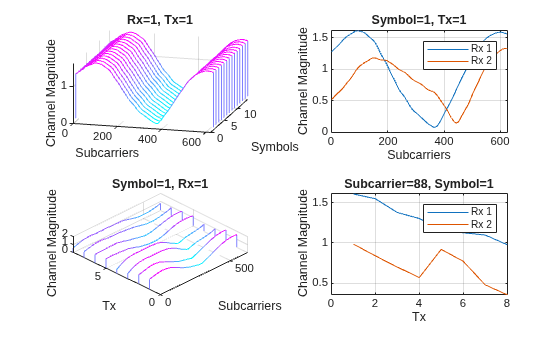
Plot the channel response. The upper left plot shows the channel frequency response as a function of time (symbols) for receive antenna 1 and transmit antenna 1. The lower left plot shows the channel frequency response as a function of transmit antennas for symbol 1 and receive antenna 1. The upper right plot shows the channel frequency response for all receive antennas for symbol 1 and transmit antenna 1. The lower right plot shows the change in channel magnitude response as a function of transmit antennas for all receive antennas for a subcarrier and symbol 1.
helperPlotChannelResponse(Hest)
Generate Channel Realizations in Bulk
The helper3GPPChannelRealizations function generates frames of channel realizations, where each frame contains slotsPerFrame slots. Set the number of samples to be generated for the data set.
dataParams.NumFrames = userParams.NumFrames;
If you have a license for Parallel Computing Toolbox™, you can enable useParallel and use parfor to parallelize data generation in the helper3GPPChannelRealizations function. Data generation takes about 4 minutes for 15000 samples on a PC with Intel® Xeon® W-2133 CPU @ 3.60GHz and running in parallel on eight workers.
useParallel =  true;
true;Enable saveData to save the channel realizations to .mat files. Otherwise, the generated data is stored in a local variable.
saveData =true; dataDir = fullfile(pwd,"Data"); dataFilePrefix = "nr_channel_est";
Generate independent realizations of the channel for the selected delay profile.
resetChannel = true;
Generate channel realizations. If saveData is true, return a datastore that contains the generated files. Otherwise, return an array that contains the generated data.
data = helper3GPPChannelRealizations(...
    dataParams.NumFrames, ...
    channel, ...
    carrier, ...
    UseParallel=useParallel, ...
    SaveData=saveData, ...
    DataDir=dataDir, ...
    DataFilePrefix=dataFilePrefix, ...
    NumSlotsPerFrame=slotsPerFrame, ...
    ResetChannelPerFrame=resetChannel);
Removing invalid data directory: /tmp/Bdoc26b_3351752_2863012/tp52f7f4a9/5g-ex43801460/Data
Starting channel realization generation
1 worker(s) running
00:00:01 - 10% Completed
00:00:02 - 20% Completed
00:00:03 - 30% Completed
00:00:05 - 40% Completed
00:00:06 - 50% Completed
00:00:07 - 60% Completed
00:00:09 - 70% Completed
00:00:10 - 80% Completed
00:00:11 - 90% Completed
00:00:13 - 100% Completed
00:00:13 - 100% Completed
If saveData is true, display the signal datastore and save meta data.
if saveData
    data
    save(fullfile(dataDir,"data_info.mat"),"systemParams","dataParams")
end
data =
  signalDatastore with properties:

                       Files:{
                             ' .../tp52f7f4a9/5g-ex43801460/Data/nr_channel_est_1.mat';
                             ' .../tp52f7f4a9/5g-ex43801460/Data/nr_channel_est_10.mat';
                             ' .../tp52f7f4a9/5g-ex43801460/Data/nr_channel_est_100.mat'
                              ... and 997 more
                             }
                     Folders: {'/tmp/Bdoc26b_3351752_2863012/tp52f7f4a9/5g-ex43801460/Data'}
    AlternateFileSystemRoots: [0×0 string]
                    ReadSize: 1
              OutputDataType: "same"
           OutputEnvironment: "cpu"
Further Exploration
This example shows how to generate channel realizations for a MIMO OFDM channel. After generating the channel, you can preprocess these channel realizations to train channel compression or channel prediction neural networks.
If you want to train channel compression neural networks, go to Preprocess Data for AI-Based CSI Feedback Compression.
If you want to train eigen vector based (implicit) channel compression neural networks, go to Preprocess Data for AI Eigenvector-Based CSI Feedback Compression.
If you want to train channel prediction neural networks, go to Preprocess Data for AI-Based CSI Prediction.
Helper Functions
The example uses this helper function:
helper3GPPChannelRealizations— Generates channel realizations in bulk
Local Functions
function helperPlotChannelResponse(Hest)
% helperPlotChannelResponse Plot channel response

figure()
tiledlayout(2,2)
nexttile
waterfall(abs(Hest(:,:,1,1))')
xlabel("Subcarriers");
ylabel("Symbols");
zlabel("Channel Magnitude")
view(15,30)
colormap("cool")
title("Rx=1, Tx=1")
nexttile
plot(squeeze(abs(Hest(:,1,:,1))))
grid("on")
xlabel("Subcarriers");
ylabel("Channel Magnitude")
if size(Hest,3) == 2
    legend("Rx 1", "Rx 2")
elseif size(Hest,3) == 4
    legend("Rx 1", "Rx 2", "Rx 3", "Rx 4")
end
title("Symbol=1, Tx=1")
nexttile
waterfall(squeeze(abs(Hest(:,1,1,:)))')
view(-45,75)
grid("on")
xlabel("Subcarriers");
ylabel("Tx");
zlabel("Channel Magnitude")
title("Symbol=1, Rx=1")
nexttile
nSubCarriers = size(Hest,1);
subCarrier = randi(nSubCarriers);
plot(squeeze(abs(Hest(subCarrier,1,:,:)))')
grid("on")
xlabel("Tx");
ylabel("Channel Magnitude")
if size(Hest,3) == 2
    legend("Rx 1", "Rx 2")
elseif size(Hest,3) == 4
    legend("Rx 1", "Rx 2", "Rx 3", "Rx 4")
end
title("Subcarrier=" + subCarrier + ", Symbol=1")
end
References
[1] T. S. Rappaport, Wireless Communications: Principles and Practice, 2nd ed. Upper Saddle River, NJ, USA: Prentice Hall, 2002.

