Phase/Frequency Offset
R2026bApply phase and frequency offsets to complex baseband signal
Phase/Frequency Offset block
To add a block to a model, double-click the canvas and start typing the block name. Then, select the block from the list.
Libraries:
Communications Toolbox /
RF Impairments Correction
Communications Toolbox /
RF Impairments and Components
Description
The Phase/Frequency Offset block applies phase and frequency offsets to a complex signal.
This icon shows the block with all ports enabled.![]()
Examples
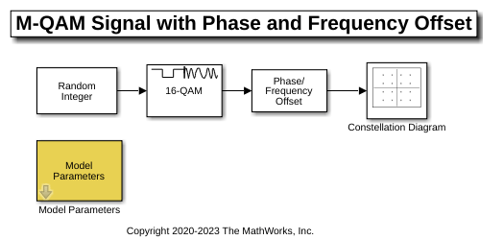
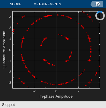
The model applies phase and frequency offsets to a 16-ary quadrature amplitude modulation (16-QAM) signal. The Phase/Frequency Offset block applies phase and frequency offsets to the input signal based on parameter settings specified in the Model Parameters block. The effects of updating the offset settings are illustrated by constellation diagrams of a 16-QAM signal.
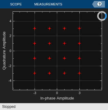
This constellation diagram shows the 16-QAM constellation with no phase or frequency offset impairing the modulated signal. The constellation diagram shows symbols with no impairments.
Modulation order: 16 Sample time: 1.00e-03 Phase Offset (deg): 0.00 Frequency Offset (Hz): 0.00
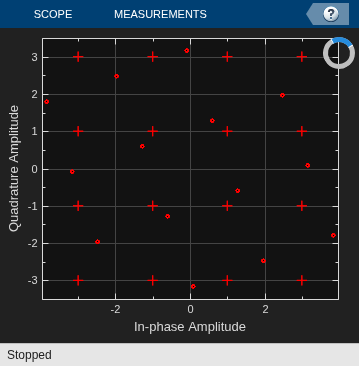
A phase offset impairs each point in the constellation, causing a rotation in the counterclockwise direction for a positive phase offset. The constellation shows the signal impaired by these settings.
Phase Offset (deg): 20.00 Frequency Offset (Hz): 0.00
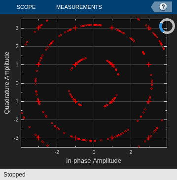
A frequency offset changes the angles of points in the constellation linearly over time, causing points in the constellation to shift radially in the counterclockwise direction for a positive frequency offset. Although the points are radially shifted, their magnitude is unchanged. The constellation shows the signal impaired by these settings.
Phase Offset (deg): 0.00 Frequency Offset (Hz): 0.50
Apply both phase and frequency offset. The constellation shows the signal impaired by these settings.
Phase Offset (deg): 20.00 Frequency Offset (Hz): 0.50
Ports
Input
Input signal, specified as a scalar, an NSamp-by-1 vector, or an NSamp-by-NChan matrix. NSamp is the number of input samples per channel and NChan is the number of channels. Each channel must have the same number of samples.
This port is unnamed on the block until you enable the Frequency offset from port parameter.
When you input a variable-size signal:
The frame size (number of rows) of the signal can change during simulation but the number of channels (columns) must remain constant.
You must set the offset parameters to be either a scalar or a 1-by-NSamp vector. NSamp is the number of samples in the input signal.
For more information, see Variable-Size Signal Support.
Data Types: double | single
Complex Number Support: Yes
Frequency offset, specified as a scalar, a vector with the same number of rows or columns as the input signal, or a matrix with the same dimensions as the input signal. For more information, see Interdependent Offset-I/O Dimensions.
Dependencies
To enable this port, select the Frequency offset from port parameter.
Data Types: double | single
Output
Output signal, returned as a scalar, vector, or matrix. This output is the same dimension and data type as the input signal.
This port is unnamed on the block.
Parameters
To edit block parameters interactively, use the Property Inspector. From the Simulink® Toolstrip, on the Simulation tab, in the Prepare gallery, select Property Inspector.
Phase offset in degrees, specified as a scalar, vector, or matrix.
If Phase offset (deg) and Frequency offset (Hz) are both nonscalar, they must be the same size.
Tunable: Yes
Select this parameter to add the Frq port.
When you select this parameter, the Frq port specifies the frequency offset.
When you clear this parameter, the Frequency offset (Hz) parameter specifies the frequency offset.
Frequency offset in hertz, specified as a scalar, a vector with the same number of rows or columns as the input signal, or a matrix with the same dimensions as the input signal. For more information about the maximum recommended offset, see Frequency Offset and Baseband Bandwidth Considerations. For more information about the property dimensions, see Interdependent Offset-I/O Dimensions.
If Phase offset (deg) and Frequency offset (Hz) are both nonscalar, they must be the same size.
Tunable: Yes
Dependencies
To enable this port, clear the Frequency offset from port parameter.
Type of simulation to run, specified as Code generation or
Interpreted execution.
Code generation— Simulate the model by using generated C code. The first time you run a simulation, Simulink generates C code for the block. The model reuses the C code for subsequent simulations unless the model changes. This option requires additional startup time, but the speed of the subsequent simulations is faster than with theInterpreted executionoption.Interpreted execution— Simulate the model by using the MATLAB® interpreter. This option shortens startup time, but the speed of subsequent simulations is slower than with theCode generationoption. In this mode, you can debug the source code of the block.
For more information, see Interpreted Execution vs. Code Generation (Simulink).
Block Characteristics
Data Types |
|
Multidimensional Signals |
|
Variable-Size Signals |
|
More About
This table outlines the interdependency of offset impairment-to-input signal dimensions. NSamp is the number of samples per channel in the input signal and NChan is the number of channels.
| Data I/O Dimension | Frame Size | Number of Channels | Acceptable Dimension of Frequency Offset and Phase Offset Impairment |
|---|---|---|---|
| Scalar | 1 | 1 | Scalar |
| NSamp-by-1 | NSamp | 1 | 1-by-1 NSamp-by-1 |
| 1-by-NChan | 1 | NChan | 1-by-1 1-by-NChan |
| NSamp-by-NChan | NSamp | NChan | 1-by-1 1-by-NChan NSamp-by-1 NSamp-by-NChan |
For example, when you specify a phase offset or frequency offset:
As a scalar, the same offset is applied to all elements of the input signal.
As a 10-by-1 vector for a 10-by-3 input signal, each input channel applies the same set of offsets per sample. Specifically, the same offset is applied across the three channels.
As a 1-by-3 vector for a 10-by-3 input signal, channels can define a specific offset per channel to apply to all samples in each channel.
As a 10-by-3 matrix for a 10-by-3 input signal, the offsets are applied element-wise to the input signal.
When you vary the input signal length, the offset must be either a scalar or a 1-by-NSamp vector.
When you use the Phase/Frequency Offset block to simulate a carrier frequency offset (CFO) between a transmitter and receiver, the frequency shift operates circularly on the discrete baseband signal. Spectral content that shifts beyond the edge of the baseband bandwidth, as defined by the sample rate, wraps around to the opposite edge of the spectrum.
This circular behavior is physically accurate only when the frequency offset is small compared to the guard band of the signal. If the offset exceeds the guard band, energy wraps around from one band edge to the other, producing an artifact that does not occur in a real system. In a physical receiver, the frequency range beyond the passband of the transmitted signal contains noise or adjacent-channel interference.
To avoid an artifact containing a wrapped copy of the transmitted signal:
Ensure the frequency offset is smaller than the guard band on each side of the signal.
For larger offsets, model an anti-alias filtering in the receiver by upsampling the transmitted signal to a higher rate before applying the offset, then filter and decimate the signal back to the original rate. This anti-alias filtering correctly discards out-of-band energy instead of wrapping it around.
Tips
For faster execution of the Phase/Frequency Offset block, set the Simulate using parameter to:
Code generationwhen the Frequency offset (Hz) parameter is specified via mask dialog and the Input signal has less than 2000 samples per channel.Interpreted executionwhen the Frequency offset (Hz) parameter is specified via mask dialog and Input signal has more than 2000 samples per channel.
Algorithms
If the input signal is u(t), then the output signal is
where f(t) is the frequency offset, and φ(t) is the phase offset.
The discrete-time output is given by
where i > 0, and Δt is the sample time.
Extended Capabilities
The Frequency offset (Hz) and Phase offset (deg) parameters are tunable in normal mode, accelerator mode, and rapid accelerator mode. If you use the Simulink Coder™ rapid simulation (rsim) target to build an RSIM executable, then you can tune these parameters without recompiling the model. For more information, see Tunable Parameters (Simulink).
Version History
Introduced before R2006aThis support enables you to vary the length of the input signal each time the block executes in the simulation. For more information, see input signal In.
The Phase/Frequency Offset block issues a warning that support for NChan-by-1 and 1-by-NSamp frequency offset and phase offset impairment dimensions will be removed in a future release. NSamp is the number of samples per channel in the input signal and NChan is the number of channels.
Instead transpose impairment vector dimension to 1-by-NChan and NSamp-by-1.
See Also
Blocks
- I/Q Imbalance | Free Space Path Loss | Memoryless Nonlinearity | Phase Noise | Receiver Thermal Noise
Objects
MATLAB Command
You clicked a link that corresponds to this MATLAB command:
Run the command by entering it in the MATLAB Command Window. Web browsers do not support MATLAB commands.
Seleccione un país/idioma
Seleccione un país/idioma para obtener contenido traducido, si está disponible, y ver eventos y ofertas de productos y servicios locales. Según su ubicación geográfica, recomendamos que seleccione: .
También puede seleccionar uno de estos países/idiomas:
Cómo obtener el mejor rendimiento
Seleccione China (en idioma chino o inglés) para obtener el mejor rendimiento. Los sitios web de otros países no están optimizados para ser accedidos desde su ubicación geográfica.
América
- América Latina (Español)
- Canada (English)
- United States (English)
Europa
- Belgium (English)
- Denmark (English)
- Deutschland (Deutsch)
- España (Español)
- Finland (English)
- France (Français)
- Ireland (English)
- Italia (Italiano)
- Luxembourg (English)
- Netherlands (English)
- Norway (English)
- Österreich (Deutsch)
- Portugal (English)
- Sweden (English)
- Switzerland
- United Kingdom (English)