margin
Margen de ganancia, margen de fase y frecuencias de cruce
Sintaxis
Descripción
Gráficas de márgenes
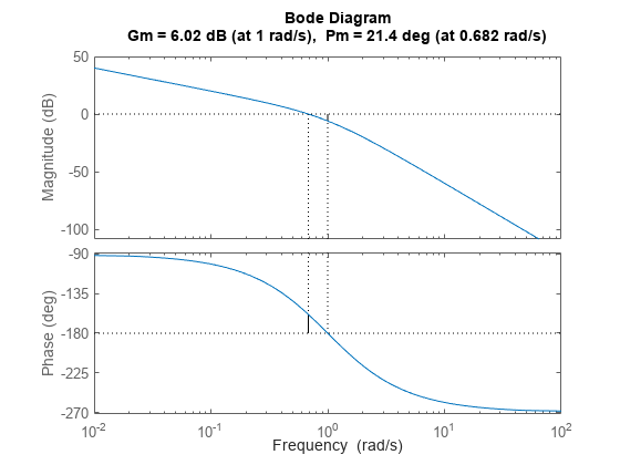
margin( representa la respuesta de Bode de sys)sys en la pantalla e indica los márgenes de ganancia y fase en la gráfica. Los márgenes de ganancia se expresan en dB en la gráfica.

Las líneas verticales continuas marcan el margen de ganancia y el margen de fase. Las líneas verticales discontinuas indican las ubicaciones de Wcp, la frecuencia donde se mide el margen de fase, y Wcg, la frecuencia donde se mide el margen de ganancia. El título de la gráfica incluye la magnitud y la ubicación del margen de fase y ganancia.
Gm y Pm de un sistema indican la estabilidad relativa del sistema de lazo cerrado que se formó aplicando retroalimentación negativo unitario a sys, como se muestra en la siguiente figura.

Gm es la cantidad de varianza de ganancia necesaria para unir la ganancia de lazo en la frecuencia Wcg, donde el ángulo de fase es –180° (módulo 360°). Dicho de otra forma, el margen de ganancia es 1/g si g es la ganancia en la frecuencia de fase –180°. Del mismo modo, el margen de fase es la diferencia entre la fase de la respuesta y –180° cuando la ganancia de lazo es 1,0. La frecuencia Wcp a la que la magnitud es 1,0 se denomina frecuencia de unidad-ganancia o frecuencia de cruce de ganancias. Cuando sys tiene más de un cruce, margin indica las frecuencias con un margen de ganancia más cercano a 0 dB y un margen de fase más cercano a 0°.
Generalmente, los márgenes de ganancia de tres o más combinados con los márgenes de fase entre 30° y 60° resultan ser tradeoffs razonables entre ancho de banda y estabilidad. Sin embargo, en algunos sistemas multivariables, la estabilidad se puede perder a una frecuencia diferente para variaciones de ganancia y fase mucho menores. En estos sistemas, la noción de márgenes de disco proporciona estimaciones más fiables de los verdaderos márgenes de ganancia y fase. Para más información sobre márgenes de disco, consulte diskmargin (Robust Control Toolbox).
Valores de márgenes
[ devuelve el margen de ganancia Gm,Pm,Wcg,Wcp] = margin(sys)Gm en unidades absolutas, el margen de fase Pm y las frecuencias correspondientes Wcg y Wcp de sys. Wcg es la frecuencia en la que se mide el margen de ganancia, que es una frecuencia de cruce de fases de –180°. Wcp es la frecuencia en la que se mide el margen de fase, que es una frecuencia de cruce de ganancias de 0 dB. Estas frecuencias se expresan en radianes/TimeUnit, donde TimeUnit es la unidad especificada en la propiedad TimeUnit de sys. Cuando sys tiene varios cruces, margin devuelve los márgenes de ganancia y fase más pequeños y las frecuencias correspondientes.
margin devuelve una advertencia si el sistema no es estable internamente, si el lazo cerrado no es estable o contiene cancelaciones de polos y ceros fuera de la mitad izquierda abierta del plano.
[ calcula los márgenes de ganancia y fase en el rango de frecuencia [Gm,Pm,Wcg,Wcp] = margin(sys,Focus=[fmin,fmax])fmin,fmax], ignorando los problemas de estabilidad fuera de este rango. Por ejemplo, utilice esta sintaxis para ignorar la dinámica de muy baja frecuencia a fin de calcular los márgenes de estabilidad. (desde R2024a)
[ deriva los márgenes de ganancia y fase de los datos de respuesta en frecuencia. Proporcione los datos de ganancia Gm,Pm,Wcg,Wcp] = margin(mag,phase,w)mag en unidades absolutas y los datos de fase phase en grados. Puede proporcionar el vector de frecuencia w en cualquier unidad, y margin devuelve Wcg y Wcp en las mismas unidades.
Ejemplos
Argumentos de entrada
Argumentos de salida
Sugerencias
Cuando utiliza
margin(mag,phase,w),marginse basa en la interpolación para aproximar los márgenes, que suelen generar resultados menos precisos. Por ejemplo, si no hay cruce de 0 dB dentro del rango dew,margindevuelve un margen de fase deInf. Por lo tanto, si tiene un modelo analíticosys, utilizar[Gm,Pm,Wcg,Wcp] = margin(sys)es una forma más fiable de obtener los márgenes.Si tiene instalado Robust Control Toolbox™, puede utilizar
diskmargin(Robust Control Toolbox) para calcular márgenes basados en disco que definan un rango de variaciones de ganancia y fase "seguras" para las que el lazo de retroalimentación permanezca estable.
Historial de versiones
Introducido antes de R2006aConsulte también
bode | allmargin | diskmargin (Robust Control Toolbox) | Linear System Analyzer
