How to Improve Accuracy in Visual SLAM
R2026bAchieving reliable real-time localization and mapping is essential for robotics and AR applications. Computer Vision Toolbox™ provides a performant, configurable, and easy-to-use interface that offers an out-of-the-box solution for visual simultaneous localization and mapping (vSLAM), handling tasks such as feature extraction, matching, pose estimation, mapping, loop closure, and IMU sensor fusion internally. To meet performance demands, you can improve the accuracy, robustness, and efficiency of your visual SLAM system by optimizing sensor use for loop closure and tuning key parameters. For a general description on what SLAM is and how it works for different applications, see What is SLAM?
Using Verbose Mode to Diagnose SLAM Errors
During SLAM processing, you can diagnose and troubleshoot errors using runtime
messages returned to the command line as the algorithm runs. To display these messages,
set the Verbose property of your monovslam,
stereovslam, or rgbdvslam
object to 1.
This table lists some of the most common messages and root causes you might encounter and some of their possible root causes.
| Verbose Message | Root Cause | Parameters to Tune |
|---|---|---|
| If, the count of tracked features or points falls below a critical threshold, this can result in initialization failures or a loss of tracking. Factors that can contribute to this include: inadequate image quality, abrupt variations in brightness, or rapid movements. To mitigate this problem, consider extracting a larger number of 2-D features, or reduce the number of frames skipped between each pair of keyframes. |
See SLAM Initialization and Tune Keyframe and Tracking Parameters. |
| Loop closure failures typically arise from these primary factors:
When other methods do not yield sufficient performance, consider generating a new bag-of-words model using data from a camera sensor with characteristics similar to the target sensor. |
See Loop Closure. |
| Loss of tracking can occur due to these factors:
Use |
|
In addition to enabling Verbose mode, see Techniques to Improve Accuracy for common sources of inaccuracy and ways to improve SLAM accuracy.
Sources of Inaccuracy in SLAM
Achieving high accuracy in visual SLAM is challenging because errors can arise from many sources. Issues with sensor calibration, data association, or environmental complexity can all lead to drift or inaccurate maps. Understanding where these inaccuracies originate is the first step toward improving system performance. Factors that can affect the accuracy of SLAM systems include:
Camera Calibration — Inaccurate camera calibration, such as errors in intrinsic parameters, can lead to incorrect pose estimation and mapping results.
SLAM Initialization — Issues during initialization. If the system cannot extract or reliably match enough visual features between initial frames, it might struggle to track motion or build a consistent map.
Tracking and Keyframe Management — You can lose tracking due to factors such as motion blur, fast camera movements, or scenes with few distinctive visual features.
Loop Closure — A missed loop closure can occur if the system either fails to recognize that it has revisited a location (a false negative) or erroneously identifies a loop closure (a false positive). In both cases, the system might not property correct accumulated errors in its position estimate.
Visual-Inertial SLAM (Sensor Fusion) — Poor sensor fusion between camera and IMU data in SLAM often results from IMU calibration and incorrect noise models.
Techniques to Improve Accuracy
To improve SLAM accuracy, you must optimize several key components of the system. Optimization includes techniques such as camera calibration, initialization, tracking and keyframe management, loop closure, and visual-inertial sensor fusion, each contributing to more reliable and precise mapping and localization.
Camera Calibration Accuracy
Accurate camera calibration in SLAM ensures precise mapping of 3-D environments and reliable pose estimation. A camera calibration is accurate when the reprojection error is low, typically below one pixel, and remains evenly distributed across all images. Undistorting images that contain straight lines should preserve their straightness, with no bending or structured artifacts. The calibration should also perform reliably in downstream tasks, such as pose estimation or SLAM, and should not introduce curvature, drift, or scale inconsistencies.
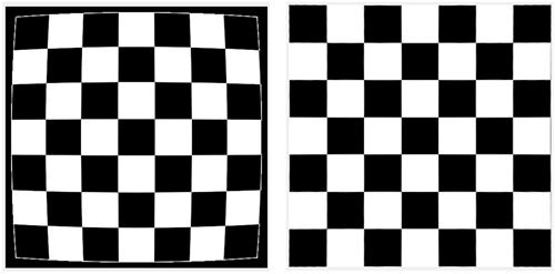
Image quality directly affects the accuracy of SLAM and other feature-based computer vision tasks. Lens distortion can bend straight lines and bias feature detection, reducing geometric consistency across images. To improve image quality and downstream accuracy, undistort images using the camera parameters obtained from calibration. Image undistortion removes lens distortion and preserves scene geometry, enabling feature detection and matching with corrected images.
Use the undistortImage function with
the distorted image and the cameraParameters object to generate an undistorted image. This
correction ensures that straight lines in the real world appear straight in the
image.
Fisheye images introduce strong lens distortion that can reduce feature
tracking accuracy and geometric consistency. To improve SLAM accuracy and
compatibility, convert fisheye images to a standard pinhole model using the
undistortFisheyeImage function with parameters estimated from
fisheye calibration. This conversion generates new intrinsic parameters
corresponding to the equivalent pinhole camera model. Providing these
undistorted images and updated parameters to the monovslam object ensures compatibility with algorithms designed
for pinhole cameras while maintaining accurate feature detection and
tracking.
For more details about fisheye calibration, see Fisheye Calibration Basics.

SLAM Initialization
SLAM initialization establishes the first reference frame and creates the initial 3-D map of the environment. During this phase, the system detects and matches visual features to estimate the camera pose and the positions of scene keypoints. A good initialization means that the position of the camera is stable and does not jump around unexpectedly. It also requires a nondegenerate baseline between the first keyframes, which means the camera must move enough so that you can clearly estimate the 3-D structure of the scene. In addition, you want the points in the map to be well-triangulated, with positive depth and enough parallax for accurate reconstruction. If you can track the first few frames reliably, and the map does not quickly collapse, change shape, or scale incorrectly, then the initialization is sufficient for normal SLAM operation to continue.
Tracking and Keyframe Management
Tracking and keyframe management are critical components of SLAM systems. Tracking estimates the motion of the camera over time, while keyframes are selected frames that capture significant changes in viewpoint and serve as stable reference points to maintain map consistency and support robust localization. The methods for managing tracking and keyframes are described in these techniques:
Loop Closure
Loop closure is a process in SLAM that detects when the camera revisits a previously mapped area. By recognizing these revisits, the system can correct accumulated drift and refine both the trajectory and the map, ensuring consistency. Loop closure typically runs in the background using feature-based place recognition, matching visual features from the current view against those from past keyframes. Effective loop closure significantly improves the accuracy and robustness of SLAM in large or repeatedly traversed environments.
Visual-Inertial SLAM (Sensor Fusion)
Visual-inertial SLAM uses both camera and IMU data to improve motion tracking. By combining these measurements, the system stays accurate even during rapid motion or challenging visual conditions, where feature extraction degrades. These key techniques enable you to leverage IMU data and optimize its integration:
IMU initialization in monocular visual-inertial SLAM involves estimating both gravity rotation and pose scale. These steps are essential to resolve the scale ambiguity inherent in monocular vision and to align inertial and visual data within a consistent reference frame.
Gravity rotation — The gravity rotation estimation aligns the inertial measurements with the visual data, ensuring the orientation of the system reflects the true gravitational direction. This alignment is essential for accurate motion estimation because accelerometer readings include the constant acceleration due to gravity, which does not represent actual motion and must be removed before sensor fusion.
Since the input pose reference frame might not match the IMU local navigation frame, typically north–east–down (NED) or east–north–up (ENU), in which you know the gravity direction, you must to transform the estimated camera poses to the local navigation frame to remove the known gravity effect. The estimated rotation provides this transformation, aligning the input pose reference frame to the IMU local navigation reference frame.
The
monovslamobject stores the estimated gravity alignment has returned in theGravityRotationproperty. When this alignment is successfully estimated, theIsIMUAlignedproperty value istrue.Pose scale — Estimation determines the real-world metric scale of the scene, enabling accurate and drift-free 3-D reconstruction and trajectory estimation.
For monocular systems, estimating the pose scale is necessary because you cannot directly infer the real-world scale of the scene from images alone. By leveraging inertial data, the system can resolve this scale ambiguity, resulting in more accurate and reliable mapping and localization.
The
monovslamobject stores the estimated scale factor in theIsIMUAlignedproperty.
Together, the gravity rotation and pose scale estimations enable the system to produce metrically accurate 3-D reconstructions and trajectories. Note that camera-IMU fusion cannot proceed if the IMU initialization is not successful.
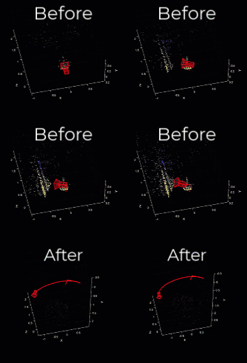
This animation illustrates the effects of properly tuning the gravity rotation and pose scale estimations by showing the SLAM trajectory before and after alignment. Once the estimation has been applied, the trajectory plot automatically updates to reflect the path in the newly aligned reference frame, incorporating the corrected (estimated) scale. This ensures that the visualized trajectory is both spatially accurate and metrically consistent with the real-world environment.
The monovslam, stereovslam, and
rgbdvslam SLAM objects automatically estimate gravity
rotation and pose scale using internally designed factor graphs. With sufficient
data coverage and appropriate tuning of the NumPosesThreshold
and AlignmentThreshold properties, you can achieve reliable
initialization with minimal user intervention.
Best Practices for Successful Camera-IMU Alignment:
You typically perform gravity rotation and pose scale estimation early in the sequence, once a sufficient number of camera poses have been collected. For more information on this calibration technique, see Gravity Rotation and Pose Scale (Navigation Toolbox).
To obtain a reliable estimation of gravity rotation and pose scale, the collected poses should satisfy these conditions:
Number of poses — Try to keep the number of poses under 30 for most cameras and frame rates. A larger number increases drift, while fewer than 10 poses might not provide enough information for a robust estimation.
Motion diversity — Include rotation around all three axes.
Vertical translation — Incorporate upward motion (opposite the gravity direction).
Pose accuracy — Ensure accurate camera pose estimates by tuning SLAM object properties, such as
TrackFeatureRangeorSkipMaxFrames.
The NumPosesThreshold and
AlignmentFraction properties control the number of camera
poses used for camera-IMU alignment. These settings determine when the alignment
process begins and how much of the available data is used, respectively.
To perform accurate calibration between the camera and IMU, you must collect a
sufficient number of camera-only poses. The NumPosesThreshold
defines the minimum number of camera poses required before alignment can begin,
while AlignmentFraction determines the proportion of the
total data set to use during the alignment process.
These properties help ensure that enough spatial and temporal information is available to reliably align the camera and IMU data streams.
NumPosesThreshold— Number of estimated camera poses required to trigger IMU alignment. Too few poses results in unstable estimates; too many can incorporate drift. Try to keep the number of poses under 30 for most cameras and frame rates. A larger number increases drift, while fewer than 10 poses might not provide enough information for a robust estimation.AlignmentFraction— Subset of the most recent poses used for alignment, specified as a scalar in the range (0, 1]. This range helps exclude early noisy estimates for more accurate calibration. The number of poses considered for alignment is:round(NumPosesThreshold*AlignmentFraction).This value effectively filters out initial, potentially noisy pose estimates, ensuring only the most relevant data contributes to the alignment for improved accuracy.
Key Takeaways for Improving SLAM Accuracy
Achieving robust and accurate SLAM depends on careful tuning and validation. After
setting parameters for camera calibration, initialization, tracking, loop closure, and
IMU fusion, validate your system by visualizing trajectories, checking for drift, and
confirming that loop closures and IMU alignment occur consistently. To compare estimated
trajectories against ground truth, you can use the compareTrajectories function.
Use the diagnostic messages, mapping visualizations, and performance metrics to identify weak points in the processing of your data and environment. Adjust parameters as needed until tracking remains stable under varying motion, lighting, and environmental conditions.
Improving SLAM accuracy is an iterative process that combines precise sensor calibration, thoughtful parameter tuning, and validation against real-world data. By systematically refining your configuration and verifying performance using the visualization and diagnostic tools in Computer Vision Toolbox and Navigation Toolbox™, you can achieve high-accuracy, real-time SLAM suitable for robotics, AR, and autonomous navigation applications.
See Also
Topics
- What Is Structure from Motion?
- Visual Localization in a Parking Lot
- Implement Visual SLAM in MATLAB
- Stereo Visual SLAM for UAV Navigation in 3D Simulation
- Stereo Visual Simultaneous Localization and Mapping
- Monocular Visual Simultaneous Localization and Mapping
- Develop Visual SLAM Algorithm Using Unreal Engine Simulation (Automated Driving Toolbox)

