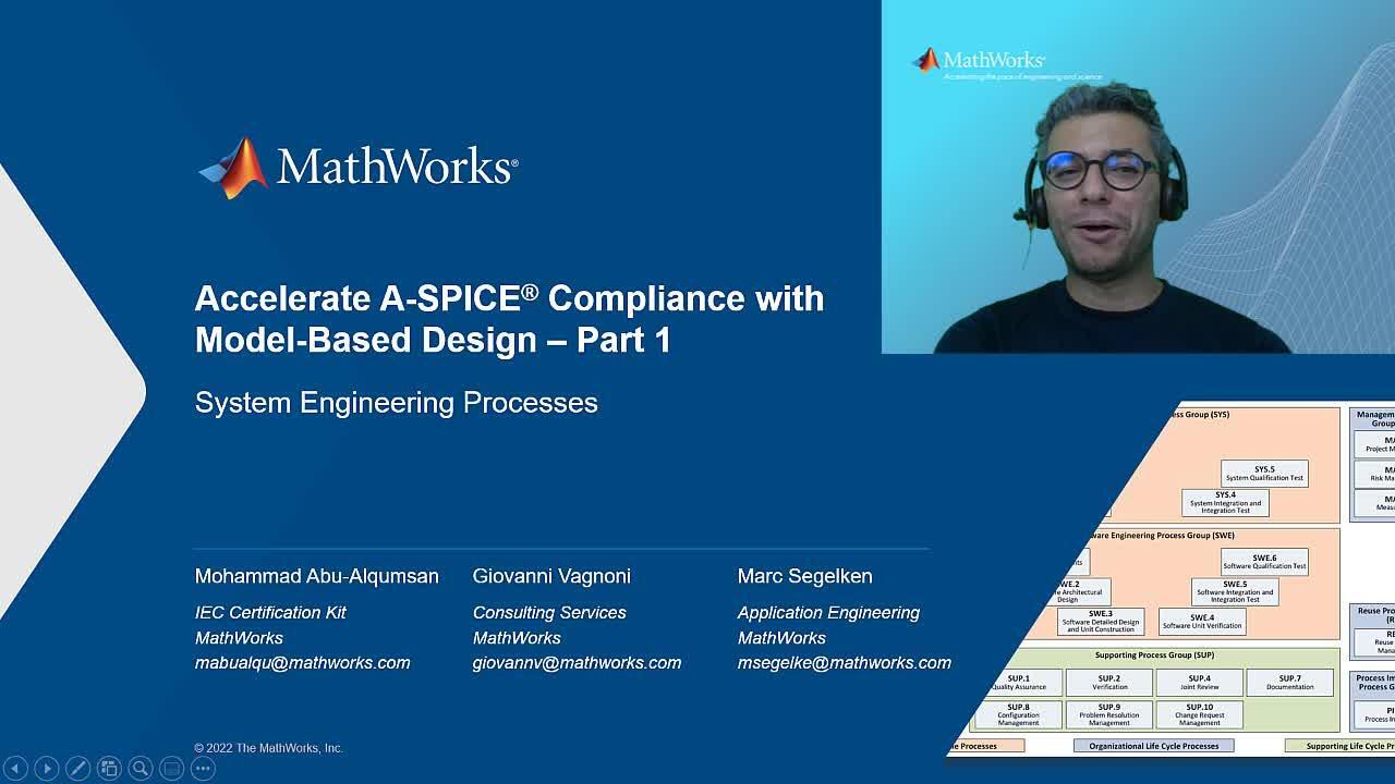
Accelerate A-SPICE compliance with Model-Based Design - Part 1/2 (Systems Engineering Processes)
Overview
This webinar is the first part of a two-parts series on using Model-Based Design to achieve compliance with Automotive SPICE. This part focuses on Systems Engineering Processes.
Automotive SPICE allows organizations across the automotive supply chain to assess and improve the capability levels of their own processes as well as those of their suppliers. Consequently, A-SPICE compliant processes allow suppliers to satisfy and even exceed customer expectations.
To effectively achieve A-SPICE compliance, organizations choose to use Simulink family of products. This is partially because automation capabilities in Model-Based Systems Engineering (MBSE) allow engineers to focus on their state-of-the-art products and innovations and leverage tooling support to achieve process quality aspects like traceability, consistency, and documentation.
Starting in R2022a, the IEC Certification Kit provides a mapping document between base practices of engineering processes in automotive SPICE and use cases of Simulink family of products.
In this webinar, we will see how these products work together in a streamlined way to support your A-SPICE compliance efforts when it comes to System Engineering Processes.
Mr. Peter Abowd from Kugler Maag will join the session to highlight some of the best practices in this space.
Highlights
- Achieve A-SPICE compliance with MBSE by performing base practices of system engineering processes
- Maintain consistency and traceability across your System architecture design and V&V artifacts with MBSE
- Ensure continuity of your system and software development artifacts
- Shift your verification to the left and detect issues as soon as they are introduced throughout the development process
- Show evidence for compliance with automatically generated artifacts
About the Presenters
Mohammad Abu-Alqumsan, Product Manager at MathWorks. Mohammad focuses on quality, safety and cybersecurity and consults with industry participants on qualifying tools and developing workflows that comply with popular certification standards such as ISO 26262, SOTIF, IEC 61508, ISO 21434 and Automotive SPICE.
Peter Abowd, CEO of Kugler Maag Cie North America. Peter’s expertise ranges from building successful global embedded software organizations and providing organizational change leadership to guiding teams in implementing practices from ASPICE, functional safety, Agile, software product lines, and CMMI.
Recorded: 28 Sep 2022
Hello, everyone. Welcome to our webinar series on "Accelerating Automotive SPICE Compliance with Model-Based Design" my name is Mohammad Abu-Alqumsan. And I am the product manager for the IEC Certification Kit here at MathWorks. I have with me today my colleagues Giovanni Vagnoni from MathWorks Consulting Services and Marc Segelken from our application engineering team. Peter Abowd is our-- today's special guest from Kugler Maag. Peter will join later for a discussion and for the Q&A session.
In today's webinar, you will learn how to use model-based design to, first, quickly develop and realize your system requirements and architectural designs; second, early verify your system designs with simulation, even during requirements specification and before the availability of some system elements; and third, to iterate over your designs and implementations to account for change, should the need for that arise.
Together, these features would accelerate your Automotive SPICE compliance and allow you to develop high-quality products that satisfy or even exceed the expectations of your customers. Before we go into more details, let's quickly revisit what ASPICE is and why we do care about it.
The modern car is a perfect example of a system of systems. Thousands of components and systems need to work together to provide all the required functionality by drivers and passengers. Estimates point to anywhere between 50 and more than 100 electronic control units, or ECUs.
Some functionality in these ECUs is developed in-house by OEMs, but several other ECUs are typically developed by suppliers to OEMs and their multi-tier network. To ensure that these systems work as initially specified when integrated together, management of internal and external suppliers is key.
Several research and empirical studies have been consistently showing that qualification testing of the final product alone is not sufficient to ensure high quality. According to these findings, product quality starts with the earliest stages of the product lifecycle. And therefore, process quality is a decisive factor in developing high quality products.
Reasons for this are manifold. Ensuring the quality and capability of the development process, you can detect issues as early as possible. This would mean less issues to fix during development or after release and less defect rate overall.
Automotive SPICE is a common framework to manage quality and determine capabilities of existing processes, and it's becoming a de facto requirement in the industry. The standard defines a process reference model with specific processes, their purposes, outcomes, base practices, and work products.
These processes are categorized in three major categories-- primary, organizational, and supporting lifecycle processes. System and software engineering processes are part of the primary processes. At the same time, the standard defines a framework for assessing the capabilities of these processes. Capability level 0 indicates that the process is incomplete. Level 1 capability indicates that the process is performed and achieves its purposes. Performance indicators from the output work products and applied base practices are used to assess achieving this capability.
Specific process aspects or attributes are used in a progressive manner to achieve higher capabilities. Capability level 5, for example, is the highest level and denotes innovating processes with continuous improvement capabilities.
Model-based design offers many capabilities and features that accelerate your compliance with the A-SPICE process reference model and improve the capabilities of your processes. In this webinar, we will highlight some of these capabilities, focusing on system engineering processes. In the next webinar, we will continue with software engineering processes.
In both webinars, we show an example of a battery system from the PowerTrain domain. The shown graphic here helps situate this example within the whole-vehicle requirements and architecture. The battery system is composed, typically, of the battery cells, their interconnections, the battery cooling and heating subsystems, and the battery management system.
System engineering processes are where activities for multiple disciplines and domains meet, including hardware, software, mechanical, thermal, et cetera. The battery system is, therefore, a good example for our case. Our next webinar will address software engineering processes, taking the battery management requirements and locate it to software further down the development path.
Here is the agenda for our webinar. Our colleague, Giovanni, will walk us through the left side of the V with SYS 1 to SYS 3. Then our colleague, Marc, will continue with the right side of the V with system integration and qualification tests. Traceability, consistency, and documentation are common ingredients in system processes. I'll take this opportunity to summarize model-based design support over these areas. After that, Mr Peter Abowd from Kugler Maag will join us for a quick discussion. We will then open the floor for your questions. So please let me hand it over to my colleague, Giovanni.
Thank you, Mohammad, for the kind introduction. Within the next 15 minutes, I'm going to tell you how MathWorks products can help you to elicitate stakeholder requirements, to specify and analyze system requirements, and to design system architectures.
Let's start with SYS.1-- requirement elicitation process. The purpose of this process is to gather, process, and track evolving stakeholder needs and requirements throughout the lifecycle of the product so as to establish a required baseline that serves as a basis for defining the needed work products.
Typically, stakeholder requirements may come from different sources and may come in different formats. With model-based design, you can easily import and export these requirements into the Simulink environment using the Requirement Toolbox.
The import and export capabilities of the Requirement Toolbox support round-trip workflows with third-party requirement management tools, using common formats like Microsoft Word or Excel files. You can use additional plugins and connectors made available by third-party requirements management tools. If these are not still suitable for your development, MathWorks Consulting Services can support you in deploying your customized solution.
Once stakeholder requirements are available in the Requirements Toolbox, we can start analysis to ensure that the customer and supplier understand each requirement in the same way. Joint review is a common practice here. In some situations, simulation and rapid prototyping can provide a great support to this activity. So let's see how model-based design enables analysis and simulation of the requirements in these early stages of the development lifecycle.
Starting from at least Release 2022a, you use the Virtual Vehicle Composer app to quickly configure a virtual vehicle for virtual prototyping purposes. You can choose between different vehicle architectures and easily set up each subsystem according to your specifications-- in other words, physical requirements.
Here are some examples for the vehicle body, the tire, the electric motor. And once the vehicle system is set up, different verification scenarios can be specified as well. You can also select quantities of interest and export all as a single model.
With this product model, you can analyze simulation results to assess system specifications in the stakeholder requirements. You can also support your analysis by adding rational and user-specific comments to existing requirements. These activities conclude when each requirement is agreed upon by customer and supplier.
Output of this activity are stakeholder requirements, baselined and available in the form of requirements set. You can explore these requirements set from this Requirement Toolbox to update the initially provided stakeholder requirements in the original format. Additionally, you can use the report generator capabilities model with design to provide the analysis reports, which may contain other requirements comments, rationals, or even simulation results.
Stakeholder requirements being available, let's continue to SYS.2. The purpose of this tool, or System Requirement Analysis process, is to transform the defined stakeholder requirements into a set of system requirements that will guide the design of the system. Stakeholder requirements, or even an initial set of system requirements, can be either imported from external sources or directly out of the Requirement Toolbox.
Let's see, now, which possibilities the Requirement Toolbox provides to specify and structure the requirements. The Requirement Toolbox allows you to organize your requirements into three structure where you can use containers to group closely related requirements together.
Further, typical requirements attributes are provided off the shelf by the Requirement Toolbox. This includes, for each requirement, an automatic index, a user-defined customer ID, a summary, a description, a rational, and the requirement type, which denotes whether a requirement is functional or not functional or a container. You can edit the description and the rationale either directly in the Requirement Toolbox or using Microsoft Word.
You can extend the associated data with each requirement by defining custom attributes for your Requirements set. This way, you can specify, for example, their ASIL level and the verification criteria for your requirements.
When it comes to analyzing the requirements, will design offers wide range of simulation and automation capabilities. Let's see, now, two examples.
In this first example, you will see how to define stakeholder requirements, simulations in model-based design. Imagine that the stakeholder requires you to develop a battery system providing an electric driving range greater than 300 kilometers, and then electric power so that the vehicle can accelerate from 0 to 100 kilometers per hour in less than 8 seconds.
With Simulink, you can visually prototype this vehicle system, including the battery itself. With help of the virtual prototype and Optimization Toolbox, you will be able to optimize some of your system parameters.
In this example, I want you to find the optimal number of cells in series and in parallel of my battery system so that the energy consumption and costs are minimized while meeting the stakeholder requirements. You can then specify and refine the requirements regarding a number of serious and parallel cells in the Requirement Toolbox. Further, you can establish a link to the world optimization analysis and optimization performed.
In the second example, let's see how to refine a set of logical and closely related requirements for a DC-charging court of an electric vehicle. To this end, you specify your system requirements with the help of the requirement table and the Requirement Toolbox.
Each row of the table defines the requirements, which includes the summary field, which is a text-based description of the requirements, a precondition, which is an expression that defines the conditions-- whether the requirement is active. This expression is written using Matlab code.
An optional duration, which describes time in seconds during the precondition must be satisfied. A postcondition, which is an expression that defines a condition that must be achieved when precondition is met.
You can also express variable range using standard syntax, such as parentheses and brackets. You can analyze the table for consistency and completeness using Simulink Design Verifier. The results are shown in the report and highlighted in the table.
You can also specify assumptions to define physical constraints of the system while performing the analysis. This features analysis from model-based design help you to specify and refine your system requirements, including related system interfaces. Once requirements analysis is complete and stakeholder requirements are refined, you may want to check the traceability to ensure consistency and completeness of your system requirements.
The Requirement Toolbox allows you to automatically generate traceability diagrams to check the different refinement levels and traceability metrics to identify and eventually correct relationships between the requirements. Traceability diagrams and metrics are not limited to requirements only. They can be generated for all the artifacts linked to a requirement, such as interfaces and parameters, data dictionaries, elements of the design models, and the specifications, as you will see later.
The outputs of this tool are complete, consistent, and refined requirements, available as requirements set in the Requirement Toolbox. This includes analysis artifacts and verification criteria as well. You can also, at this stage, export the visibility diagrams and matrices you saw earlier.
Let's now proceed to the SYS.3. The purpose of these three, or System Architecture Design Process, is to establish a system architecture design to identify which system requirements are to be allocated, which elements of the system, and to evaluate system architectural design against defined criteria. In the next few slides, you will see how to design different system architectures, how to view the system architectures from different perspectives, and how to specify the system interfaces.
Engineering the architecture for a large and complex system, such as a vehicle or a battery system, is a demanding undertaking. System architects must perform many tasks and use many techniques to create a sufficient set of architectural models.
Typically, designing a system architecture goes in parallel with the requirement specification activity. The system's well-trod paths between requirements through a space and architecture design. In solution space, some typical system elements are already available.
Starting from stakeholder requirements, functional requirements specification may be supported by a functional architecture and related models. The simulation may allow the analysis and refinement of those requirements that you've seen before.
As a result, more refined system requirements and the logic architecture are designed. System requirements are then broken down, with the help of a physical architecture, into hardware and software requirements.
Let's see now how System Composer can effectively and efficiently support these activities. This is an example model of the battery system connected through required interfaces with its operating environment. Let's take this example to explore, for the system under consideration, the different architectural models we have seen before-- the function, the logical, and the physical with the help of the Allocation Editor in the System Composer.
Moving the cursor to the Location Links symbol on the top right of the components provides a quick list of allocated elements. You can easily navigate between these by following the hyperlinks. You can also do your locations in a holistic manner through the Allocation Editor.
The Metrics view lets you review and modify the mapping between architectural elements, such as components and ports. You can use the filtering mechanism to focus on certain aspects of your design.
With every architectural design model, you may want to use the requirement perspective to view the allocated requirements to the architectural elements. You can also use this perspective to easily drag and drop requirements to these elements. Moving the cursor to the top right symbol of the component displays already allocated, requirements and clicking on the hyperlinks, you can review the requirements and specifications.
As part of the architecture design, you need also to specify the interfaces between system elements. Using your architectural modeling, you can use System Composer to automatically import the pinout and interfaces of a component based on its supply specification sheets.
Once other architectures have been designed and specified, you may want to analyze them. One possibility towards this end is to use profiles and stereotypes in System Composer. You can define stereotypes using the Profile Editor. You can group stereotypes and assign them different properties. You can reuse properties in these stereotypes through inheritance.
After you import a profile to your architecture model, you can apply stereotypes to your architectural elements. Using stereotypes and their properties, you can run analysis to evaluate alternative system architectures.
Here, we see an example analyzing the costs of our battery system. Another effective option to evaluate alternative system architectural designs is simulation. In case of our battery system example, you can use this battery, which is added to this Simscape family of products, starting from Release 2022b.
Simscape battery provides design tools and parameterized models for designing battery systems. You can create digital twins, run virtual tests of battery pack architectures, design battery management systems, and evaluate battery systems behavior across normal for conditions.
Battery Pack Model Builder is a design tool that lets you interactively evaluate different battery pack architectures. The tool automates the creation of simulation models that match the desired technology, and includes clean plate connections so electrical and thermal responses can be evaluated as well. After you complete your system architecture design, refine your requirements, and allocate the requirements and system elements of your designs, you may want to check again for consistency and completeness with the help of tool support for traceability.
On one side, the Requirement Toolbox allows you to automatically generate traceability methods to check and correct the allocation of requirements to the system architecture elements. On the other end, an allocation matrix, like this, lets you allocate, trace, and check architectural elements across different architectural design models. Together, Requirement Toolbox and System Composer, or Location Editor, provide you the tooling support you need to maintain consistency between the requirements and architecture awards.
The output products of this process area are system architecture design with related interfaces and allocated system requirements in System Composer. You can generate design reports and visibility matrices or design models for documentation purposes using System Composer Requirement Toolbox.
With this, I also conclude my part and will let twenty to back to Mohammad.
This was very informative. Thanks, Giovanni.
With system requirements and architectural design, including interfaces, available from SYS.2 and SYS.3 three, you are ready to distribute system elements to the different engineering domains. Requirements and system elements allocated to software are the starting point for the software engineering processes. Make sure not to miss our upcoming webinar on the topic.
Assuming, now, that system items become available, whether from hardware, software, or other domains, their integration, as well as their integration and qualification testing, should take place as part of SYS.4 and SYS.5 processes. I am glad to have our colleague, Marc, here today with us to ask him this question. Marc, can Model-Based Design help us in these processes?
Thanks, Mohammad. Yes, it can. The purpose of SYS.4-- System Integration and Integration Test-- is to produce an integrated system and to demonstrate its consistency with the system architectural design. With this, you can specify, or ideally we use test cases that have already been developed in previous process steps. You can select test cases to establish a comparison test between the simulation of the system architecture design and the integrated parts of the real system in order to demonstrate compliance.
Automotive SPICE acknowledges the stepwise integration strategy to integrate system items until you get to the full system. For a battery system, it may make sense to first integrate the battery monitoring units with a Management Controller and then with the battery disconnect unit, and later, with a charger or load. You can use some early test and test harnesses to perform these integration tests on your System Composer models.
The same steps can be, then, repeated on the real system. This lets you compare the behavior of the real system with the behavior of system models including hardware and software.
According to the standard, hardware-in-the-loop simulation and testing can support your efforts to integrate and test your system items. Hardware-in-the-loop testing lets you simulate the operating environment and system items not ready for integration yet, for which you may have a prototype or model with adequate fidelity.
It also addresses typical challenges of testing certain real system elements. Take the battery system as an example. Do you want to test the system with a real battery cell? I think the answer is obvious. Testing with real cells is associated with longer test cycles, difficult-to-reproduce results, difficult-to-test fault conditions and limited test automation and observability.
The setup you see here allows you to test the intermediate integration step of connecting the battery management ECU with the satellite battery monitoring units. In this setup, the battery cell and pack dynamics are emulated in real time. This makes it easy to quickly go through many scenarios when testing the ECU. You can incrementally enhance the setup to your reach the fully integrated battery system.
Simulation test and Model-Based Design allows you to perform integration testing in a systematic and managed way. Here you see some screenshots of how this may look like. Test results may include visual plots of certain data for interactive investigation. The test specification for vertical integration and the integration of the real system should be, within some tolerance, the same in terms of the system behavior.
Field testing can be used to compare the two setups-- the virtual against the real. You can do so by either recording test results from the testing of the virtual system and using these as expected results for the real system.
Alternatively, you can directly specify equivalence tests between both setups to perform automatic comparison of the test results. Using these features of Model-Based Design, you can automatically produce several products required by SYS.4, including traceability, test specification, and test results.
In SYS.5, you need to demonstrate the compliance of the integrated system with the system requirements from SYS.2. Acknowledging that items of the integrated system may change even after full system integration, the standard also requires regression testing during qualification testing.
Let's see an example from our battery system. We have a cycle lifetime requirement for the system allocated to our system and System Composer.
Here, you'll see the same requirement in the Requirements Editor. And also, you see and follow the link to the qualification test specification of this requirement. The integrated system has an environment which, again, can be emulated in the HIL simulation to do testing in a more efficient and reproducible way until we are ready to go on the road.
Examples for the environment for better management system are energy consumers, like the Drivetrain and body electronic system. You can use talking to target machines and similarly test and develop and execute tests. With this whole setup, you're able to observe signals which would otherwise be hard to monitor or debug with a real system. You're also able to exercise the fully integrated system in well-controlled testing environment that includes models for the driver, environment, and other systems that influence or get influenced by the battery system.
The HIL tests do not replace testing of the integrated system in the real world. But as discussed earlier, it is an efficient and effective way for early defect detection.
Here is an example qualification test scenario conducted with Simulink Test and Simulink real-time and Speedgoat target to test charge and discharge cycles. You can additionally record and summarize test specification and test results and locks using automatic report generation features of Model-Based Design. These reports include the traceability links to the tested system requirements.
In summary, you can obtain these products relevant to SYS.5. Mohammad, I think you have an overview on work products for all systems engineering processes.
That's true, Marc. It is the first part of the two overarching A-SPICE concepts we chose for today.
This list specification report Marc showed us is one example of how you can generate reports and work products using Model-Based Design.
Here is a summary of common work products which you can generate. Here are some screenshots from the requirements specification, architectural design, and qualification specification documents.
The second concept is consistency. Consistency means that work products do not contradict with each other. The bidirectional traceability between requirements and design elements and verification artifacts-- and the tools support in this regard allow you to analyze artifacts for consistency, correctness, and completeness.
Here is a summary of how Model-Based Design can support these activities as we have seen earlier. With Model-Based Design, you'll also get notified when an artifact has been modified. This allows you to quickly define and analyze the impact of this change.
So let's recap the key takeaways. Simulink family of products offers you a wide spectrum of support to quickly develop and realize your systems. You can analyze and simulate your early system designs and prototypes to verify requirements and their visibility. To support for bidirectional traceability and automation capabilities allows you to iterate over system-level activities in an efficient way.
Today, we have barely scratched the surface of how Model-Based Design can help support your A-SPICE activities. You can find a detailed mapping between the best practices of engineering processes and Model-Based Design activities in the IEC Certification Kit. In the kit, you can also find further mapping to other automotive standards, like ISO 26262, ISO 21434, and SOTIF.
For your quick reference, this slide shows a bird's eye view of the MathWorks solution to Automotive SPICE. Don't worry if you are not able to read through. We are going to share these slides after today's event.
Here is the same information in a workflow style, focusing on system-level activities. You want to develop safe products according to ISO 26262 as well? No problem. Together, this reference workflow and the IEC Certification Kit has the support you need. Feel free to check that out.
Our next webinar will cover the remaining part on software engineering processes and software engineering activities. Model-Based Design is proven and used for A-SPICE and ISO 26262. On MathWorks.com, you may find several user stories on this.
Here is a selected list from Robert Bosch and Volkswagen for your quick reference. The last link is for a talk on effective strategies for A-SPICE and Safety Compliance by Peter Abowd, our guest for today.
Great. So I see all of you or most of you did it till now. Welcome, everybody. And let's welcome our guest, Peter Abowd. Peter, it's a great honor to have you here.
Thanks. It's great to be live here with you.
Yeah, after 2 and 1/2 years break.
Yeah, we missed the human connection.
Cool. But I heard you're here for a customer visit to assess the project?
Yes, A-SPICE everywhere.
And architecture. And architecture is a big part of what teams need help with in terms of compliance. But just A-SPICE compliance aside, architecture is a critical part of designing our products for reusability for redeployment. So it's a good practice to get understood and done effectively.
And most of the time, architecture is done with models. You need models to describe architecture because that's the best way to communicate with people.
That's right. The semantics to describe it should be straightforward and easily consumable because a lot of the point of architecture is to communicate the solution of the product from a few architects to the 200 engineers that have to then do their part of it. And so, if they can't understand it, they can't do their piece. So it's critical aspect.
Yeah, I think, we'll look at A-SPICE, since we jumped SYS.1, SYS.2, and we went straight ahead to architecture.
Yeah, actually, I had one question always in mind when I look at A-SPICE. It's the stakeholder requirements in SYS.1 AND system requirements.
Yeah, what is the difference? Why? Why do we need stakeholder requirements? Why do we need system requirements? What is the system requirement?
Well, the reality is that a product team may have multiple stakeholders. One of them is the business customer, but they may have internal stakeholders like the manufacturing plant. That's a very common internal stakeholder.
And from the perspective of the standard and some of its authors, who were from the OEM, they did have, at least, a good perspective on things when they felt that, well, we may-- the customer may ask for what they want. But the reason they're buying something from you, suppliers-- because you're the expert at making that thing that they want to buy.
And so the assumption in the model is that, well, the customer is going to talk about the shiny, new things they want. And the product supplier is going to say, well yes, we can give you that. But with that, you need all these other things. We have this history of making products like this for 20 or 30-plus years. A supplier should have a database of their product requirements.
And so what they should be doing, in a quote, is, what is it that you want, customer? And OK, can we quickly correlate that to what we've already defined our product as?
And so we get a convolution of our product requirements and the customer's new requests. And that becomes the project's system requirements. And so that's the difference. The difference is, this project has a specific set of system requirements that come from this stakeholder, the customer, and possibly an internal stakeholder. And it makes a slight modification or sometimes significant modification to our history of product requirements that, then, of course, will impact our design.
I totally agree. And I think this is the pattern most of the time. Sometimes we see new products with no history. So probably, this is where-- the first time we derive system requirements from the stakeholder requirements.
Yes, which happens, but so much that goes into production is not new. It's been proven somehow, even at least in an advanced project, where you had to do some sort of requirements.
But yes, if you were doing it from scratch, you'd elicit the new requirements, the lead requirements for cutting edge ADAS features or autonomous drive. Yes, those are new. But the other 80% of the vehicle that still has to go in is not so new.
Absolutely. So you have been assisting A-SPICE projects for a long time, I assume. Where do you see organizations struggle the most? Where do you see the challenges when it comes to system-level compliance?
Right. So one of the biggest challenges is just understanding the difference between requirements and design. And I'll use the word, design, to reference system architecture, software architecture, and the detailed designs-- even the electrical and mechanical architectures.
The design is the solution. The requirements are the problem. What they want, how you create it-- so what and how?
This separation is important to understand, and it's very confused by the global use of English terms, unfortunately-- the word, requirement, or, design requirement. That's the worst phrase because what does that mean? Because if the requirements of the problem and the design is our solution, what's a design requirement?
What's a safety requirement? This really gets confusing by 26262 because they have a tendency in that standard to blur the line between a what type of requirement that's an invariant that the customer wants and your design, and some, really, constraint on your design that says, if it's going to be safe, you must do this in your design.
So sometimes it's helpful to think about the third perspective of an English word when we're talking here. Requirements, design-- if a requirement comes with a, how they want it done, that's a constraint on the requirement that constrains your solution in the way they want you to.
Safety and security, quote, "requirements" could also be viewed that way. It's a constraint on your solution.
The global use of words-- they start to take on localization meaning, and it's confusing. So a big barrier is the difference between requirements and design, especially as you throw safety and security on top of this. And so we see a lot of people struggle with that distinction.
And then it just gets worse. What's the difference between a system requirement and a software requirement and an electrical requirement?
I think now it's common practice to have safety requirements called safety requirements. They are derived from the preliminary architecture and saying, OK, how things might fail, and let's account and mitigate those errors, to take them and probably correct them. So that would be the safety requirements that they documented in textual format, and then properly implement it. You want to make sure that those requirements have been implemented at some point.
Yeah, but I agree. We have to be careful-- what is really our requirement, and what is the design constraint on top of it?
Peter, before today's meeting, I looked at your talk in MathWorks Automotive Conference in North America this year. You talked about the difference between architecture and detail design, which was mainly focusing on software.
Now, we are talking, today, about system engineering activities. Do you see any parallels between the software aspect of it and the system aspect?
Right. So the challenge, of course-- in software world, they're always talking about, when do we stop architecting, and when do we start detailed design? Well, it just escalates up to-- when we're at the system-level architecture, what's the difference between system architecture in the software architecture, especially if most of my product is software with a processor in a package?
So yes, there's problems with understanding the distinction. And now, it might be that there are those in the educated area of knowing what the difference is in system architecture and software architecture. But in the vast population of engineering in automotive space, it's not well known.
And since, good or bad, electrical and electronic and mechanical folks have tried to, as best they could, stay away from A-SPICE, their involvement was necessary all along in the system requirements and system architecture. But in their absence, some bad habits that happened were that software engineers started to do this system architecture, which is just miserable because it's missing the whole perspective.
So there are plenty of challenges that are parallel. So in the software world, the break from software architecture to detail design is not very well understood or executed, and the relationship between the system architecture and the software, electronic, and mechanical architectures are not well understood or well-executed.
I'm not saying that that's a-- everywhere a problem, but it's something I see a lot of as a problem. And that talk just replayed last week in Korea, at your Korean MathWorks Automotive Conference. So it was great. I went live with Korea at midnight or something-- my time in US, so I was still awake.
Cool. I'd think-- to really thank you for this great discussion. It's just an appetizer for you guys to put in your question in the chat. I see some of them did already, but feel free to-- we still have 15 minutes, and we are going now with your questions in the live session. My colleague-- probably, you wonder what is this empty chair. It's waiting for Giovanni whop will be moderating our Q&A session. So thank you, Giovanni.
And also, at the same time, our colleague Marc-- you have met him already in the webinar. Marc will be joining remotely.
So yeah, I pick up some questions from the Q&A and from a private chat. And yeah, the first one is for you, Mohammad. A colleague is asking if we can ensure that all the base practices of A-SPICE are fulfilled with MathWorks products. So what could be--
Yeah, so if we look at the base practices, we have the engineering practices in SYS and software levels. But some of them-- they are about communication, ensuring that some document has been transferred from the supplier to customer or from customer to supplier. So those need different mechanisms. But every engineering aspect of system and software levels you can comply with using Model-Based Design and using Simulink's family of products.
OK, thanks, Mohammad. Time for the next question, and I think I will pick up. So there was a comment-- what are we doing with simulation in SYS.1? And how do we use this outcome?
SYS.1 is about elicitating requirements. So the target there is to come with an agreement between the stakeholder and, let me say, the customer. And the task of the simulation there is really to ensure this agreement, so to put objectives on the table-- so facts rather than long talks and long discussions. We think, really, that simulation, in this stage, can really help the communication between stakeholder and customer at the end.
May I add something here?
Yes.
Not every requirement is a feasible requirement, and we see this all the time. Of course, you can start driving system requirements, go to implementation, and then figure out, oh, it doesn't really work or it doesn't make sense.
So I think simulations-- if you shift that to the left, to the earliest possible stage-- it's of a good value. Of course, sometimes, it's an overhead if your requirements are simple but I think, in complex systems, it can help you even at the stakeholder requirements
Thank you, Mohammad. Since you are happy to answer, Mohammad, let's look to the next question. So what about dynamic behavior? So how do we capture that-- the dynamic behavior between system elements? How can we describe that networks products?
I would like to tell everything I know about it. I will say something, and I guess Peter knows from projects he has seen how people can comply with it.
So Simulink and System Composer-- in the first place, when we talk about system-level activities-- it's a way to develop or to model your system elements. And then you want to model this interaction, so steady flow is one way, and the execution order is another way to look at it. The data flow between those components is another way to see how the interaction between them. Probably, I covered the big portion, but--
It was good. So the interfaces between the elements-- in A-SPICE space at the system level or the software level-- that's a very broad statement. What are the elements? And how many elements can you have? And can you have elements of elements?
And, yes, to all those questions. There could be many elements, and elements can have sub-elements. So think of that, then, as look at a Simulink. There's System Composer. Probably, more of you're familiar with Simulink. You can do architecture there as well. The Simulink blocks can be blocks of blocks. You open up the Simulink block. There's more blocks there. And the signals between them are the interfaces between those blocks.
So there you have elements, and the signals between them are the interfaces, and an element can be multi-level. So you can open up that Simulink page and see another set of blocks and, there's signals coming into that page and signals between those blocks. And so those are the interfaces, and those are probably the best defined interfaces at the system and software level that I typically see in an assessment because they have to be defined, and they have to be defined, more or less, mathematically and concretely.
So it's very simple to specify the interfaces between the elements with the Matlab tools. That's the Simulink and its partner, System Composer.
Yeah, and I don't know if you guys know about sequence diagrams in System Composer. That's another way to look at interactions between dynamic behavior of those components.
OK, thank you, Mohammad. Thank you, Peter.
Next question-- and this will challenge us. So we talked a lot about SYS and we talk about SV area. We have not talked about supporting areas. But I think there is an interesting question there. So how do we support change management, defect management? Marc, do you want to say something about this?
Sure, I can do that. So we don't have a dedicated change or defect management tool as such. Of course, you could use our requirements tool to also keep track of things like this. But maybe you want to connect to some tools that are more dedicated for this purpose, like-- for example, what I'm personally using is Jira. This can be done easily because you can link everything, for example, from Jira to requirements, components, anything test cases in Model-Based design forth and back, which means it's easy to just keep track on all the different things that have to be done and link this to some corresponding tasks in the change or defect management tool.
Thanks. Thank you, Marc. Time for the next question. And yeah, Marc, still for you. Then what happens if a component gets updated? So what should we do or how the tools can help the user to keep or to check these updates and to maybe tell us what to do next?
Yeah, the question-- especially when it comes SYS.4 and SYS.5-- especially, of course, if something needs to get updated-- which test cases do we have to rerun again? Is it really the whole set or just parts of it? And for this, of course, we can make use of the traceability information that we have because all the components are linked to requirements, and the requirements are linked to test cases.
If you like, you can also link the test cases directly to components-- for example, integration tests-- that would really make sense. So it's easy to find out which test cases make sense and need to be executed again. We don't have a dedicated list for this, but it's very easy write a small script that comes up with the corresponding test cases and rerun them, even in an automatic way, if you like.
I also have two points to add here. Thank you, Marc, for this. But we have dependency analysis, which also allows you to identify components that are affected with that change. And also, we have notification mechanisms that tells you, if you change the requirement, this component has an impact, so look there. This test has an impact. Also, look there.
OK, we have, I think, time for couple of questions more before we go to the poll. So a colleague is asking, can we achieve A-SPICE by using Matlab Simulink with other tools like those?
Yeah, for sure. I mean we offer interfaces towards third-party tools. The special case is about requirements, so requirements management. I've talked in my slides about that. So yes, we support that. And I think this is also the key for the success, so it's very important to interface with other tools to complete not only the SYS and SVE, yes, but also the supporting processes and everything that is required to achieve A-SPICE level 1, 2, 3 and more-- it will come more.
I think there are-- 4 and 5 are hours
And mentioned them.
Yeah, is there anybody complying with level 4 and 5 already?
Well, nobody checks. I think a lot of people don't understand the model, in that the point of execution is level 2. And level 3 is just a blueprint to get back to level 2. And then the other levels are just about optimizing your execution from there.
So really, getting to level 2 is a really critical point. And after that, it shouldn't be anybody else's business except the company that's doing it. So being imposed level 3 is always questionable in my view because it's just a blueprint to get back to level 2.
OK, maybe time for one last question, and it's about traceability-- I think one of the key aspects of A-SPICE. And a colleague is asking whether-- so how can exchange traceability with other tool chains? We can export traceability. So the traceability matrices that you have seen in our talk-- you can export as HTML files, and actually, is exporting data.
So behind this traceability, there are links between artifacts, links that are stored in our tools, and they are exchangeable. At least with those, we can exchange such traceability, so it's possible. Obviously, it depends on the level. Depends on the tool. But yes, such support is also there.
So with this, I think we can move to the poll.
Yeah, really thank you, Giovanni, for this. We weren't able to see all the questions while discussing with Peter, but this was really great.
I think we see, also, in the polling section-- we have three questions, so I encourage you to answer those. This will help us to provide you the guidance and the help, probably, you need to comply with A-SPICE and to improve your processes. We are continuously looking at areas that we can help, and this would help us in finding those out.
On the slide, we show, here-- it's an invite for everybody joining us today to join us also on October the 20th-- in less than a month, in Stuttgart for our automotive conference. You are all more than welcome there. And we hope to see you all there.
So with this, I think--
Next week-- part two. Software and Compliance.
So you guys, if you are interested also in software engineering or processes of A-SPICE, next week, same time, we are holding the next webinar. We will have the same format, and we hope to have it in person.
It was really great having you here.
It was nice. Yes. Wonderful.
And with that, I wish everybody good rest of the day. Thanks, Marc, for joining us remotely and helping us answering those questions. Thanks for joining.
Thanks, everyone. Bye.
Download Code and Files
Related Products
Learn More
Featured Product
IEC Certification Kit
Up Next:

Related Videos:


Seleccione un país/idioma
Seleccione un país/idioma para obtener contenido traducido, si está disponible, y ver eventos y ofertas de productos y servicios locales. Según su ubicación geográfica, recomendamos que seleccione: United States.
También puede seleccionar uno de estos países/idiomas:
América
- América Latina (Español)
- Canada (English)
- United States (English)
Europa
- Belgium (English)
- Denmark (English)
- Deutschland (Deutsch)
- España (Español)
- Finland (English)
- France (Français)
- Ireland (English)
- Italia (Italiano)
- Luxembourg (English)
- Netherlands (English)
- Norway (English)
- Österreich (Deutsch)
- Portugal (English)
- Sweden (English)
- Switzerland
- United Kingdom (English)