Deploying a Deep Learning-Based State-of-Charge (SOC) Estimation Algorithm to NXP S32K3 Microcontrollers - MATLAB & Simulink
Video Player is loading.
Current Time 0:00
Duration 34:09
Loaded: 0.48%
Stream Type LIVE
Remaining Time 34:09
 
1x
  • descriptions off, selected
  • en (Main), selected
    Video length is 34:09

    Deploying a Deep Learning-Based State-of-Charge (SOC) Estimation Algorithm to NXP S32K3 Microcontrollers

    Overview

    Battery management systems (BMS) ensure safe and efficient operation of battery packs in electric vehicles, grid power storage systems, and other battery-driven equipment. One major task of the BMS is estimating state of charge (SOC). Traditional methods for SoC estimation require accurate battery models that are difficult to characterize. An alternative to this is to create data driven models of the cell using AI methods such as neural networks.

    This webinar shows how to use Deep Learning Toolbox, Simulink, and Embedded Coder to generate C code for AI algorithms for battery SoC estimation and deploy them to an NXP S32K3 microcontroller. Based on previous work done by McMaster University on Deep Learning workflows for battery state estimation, we use Embedded Coder to generate optimized C code from a neural network imported from TensorFlow and run it in processor-in-the-loop mode on an NXP S32K3 microcontroller. The code generation workflow will feature the use of the NXP Model-Based Design Toolbox, which provides an integrated development environment and toolchain for configuring and generating all the necessary software to execute complex applications on NXP MCUs. 

    Highlights

    • Neural Network estimation for battery state-of-charge (SOC)
    • Integration of deep learning-based SOC algorithm into a Simulink model
    • Generating optimized, production ready code with Embedded Coder
    • Deploying code to an NXP S32K3 microcontroller using the NXP Model-Based Design Toolbox

    About the Presenters

    Javier Gazzarri, MathWorks

    Javier Gazzarri has worked as an application engineer at MathWorks for 10 years, focusing on the use of simulation tools as an integral part of model-based design. Before joining MathWorks, Javier worked on fuel cell modeling at the National Research Council of Canada in Vancouver, British Columbia. He has a bachelor’s degree in Mechanical Engineering from the University of Buenos Aires (Argentina), a master’s degree and a PhD degree) both from the University of British Columbia (Canada).

    Marius Andrei, NXP

    Marius Andrei joined NXP in 2017 where contributes to Model-Based Design Software solutions development for NXP Automotive Products. Marius graduated from the Politehnica University of Bucharest in Romania with a master's degree in Advanced Computer Architectures.

    Recorded: 18 Nov 2021
    Hello, everyone, and welcome to this MathWorks webinar. Thank you for sharing your valuable time with us. My name is Javier Gazzarri, and I am an application engineer at MathWorks at our Novi, Michigan office. My work focuses on modeling and simulation of battery systems. Today, I am honored with the presence of Marius Andrei, software development engineer at NXP. Hello, Marius. Would you please introduce yourself?

    Hello, Javier, and hello to everyone. My name is Marius, and I work for the Model-Based Design team here at NXP. Javier, thank you very much for inviting me to this webinar.

    Thank you, Marius, for your contribution to this event. As I said a minute ago, most of what I do at MathWorks is modeling battery systems. Why do we need to do that? Why is modeling batteries important? Let's think about this while trying to answer this question.

    How do I know how much longer I can drive my electric vehicle, use my laptop computer, or talk on my mobile phone before their lithium-ion batteries need a recharge? I look at the battery charge indicator. Despite its simple appearance, the algorithm behind the charge indicator is far from being simple, and it requires a detailed model of the battery cell behavior. Determining the remaining range of a battery pack relies on one of the most important tasks of the battery management system, the state of charge estimation.

    Despite being simple to define-- the state of charge is equal to the integral of the current divided by the total capacity-- SOC is difficult to estimate accurately. This expression, known as Coulomb counting, is only useful if the current is measured with very high accuracy and no drift. Unlike what happens with the gasoline level in a fuel tank, SOC is not directly measurable. We measure other things like voltage, current, and temperature, and calculate SOC with them in the model.

    It also requires an accurate initial condition, which typically relies on performing a periodic reset based on voltage or waiting a long time until its terminal voltage equals OCV, or Open Circuit Voltage, in which case we can do a table lookup and find SOC. Even in this case, there are problems-- for example, with cells that exhibit a flat discharge curve such as LFP.

    The state-of-the-art method for SOC estimation is the Kalman filter, whose recursive two-stage algorithm performs an estimation via Coulomb counting and a correction via voltage measurements. Although this method works very well, it requires a very accurate model of the battery cell capable of describing its behavior throughout a broad range of operating conditions, including the very challenging low-temperature case.

    Improving the accuracy of SOC estimation is the subject of much current research. One promising alternative avenue for state of charge estimation is artificial intelligence. The idea is to train a neural network to link patterns in voltage, current, and temperature to changes in SOC. In a previous webinar, we showed how to train a deep neural network to estimate battery SOC. The work was largely based on research done at McMaster University by Carlos Vidal, Phil Kollmeyer, and others, including a team at FCA. In that event, we describe the workflow to train a deep fit-forward neural network to estimate battery state of charge.

    The process involved cycling a battery cell, acquiring voltage, current, and temperature and associated information, and train a neural network with the first three signals as inputs and the SOCS output. The neural network was then tested for accuracy with data measured independently and at different temperatures. Then the trained neural network was implemented in Simulink, which is the de-facto tool for control system development and the environment in which most battery engineers develop their BMS.

    So our work back then was limited to modeling and simulation on a desktop computer. A real-world application such as range estimation in an electric vehicle demands one further step, namely to generate C code from the trained network and download this code onto a hardware target. In this webinar, we will describe the procedure to generate code from an AA-based SOC estimation algorithm for hardware developments in the new NXP S32K3 board.

    We will first place today's topic in the context of developing SOC estimation algorithms with artificial intelligence. Secondly, we will show how to import a neural network that was trained outside of the MathWorks ecosystem. And in this case, we will bring a TensorFlow-trained neural network into MATLAB, analyze it, and make an SOC prediction with it.

    In the third place, Marius will introduce the NXP Model-Based Design Toolbox for S32K3 with simple model examples. Finally, I will show how to generate code from the imported neural network, download the code onto the NXP port, and run the simulation in normal mode and in processor-in-the-loop. This is the general workflow to develop and implement an AI-based BMS task. We start gathering the experimental data from the physical system, choose the AI function we want to train-- for example, a neural network-- train it and test it, transfer it to simulate for VMS integration, cogeneration, and hardware deployment.

    During our previous webinar, my colleagues from McMaster University and I show up to here. Today, Marius and I will start from importing a neural net from TensorFlow all the way to processor-in-the-loop simulation. Let's start by importing a neural network from outside of the matrix ecosystem. Why would we want to do this? Well, while implementing AI-based designs, it is not uncommon to count on a pre-trained algorithm instead of needing to train it yourselves or to have to improve a pre-trained network with additional data in what we called transferred learning.

    As a response to this need, MathWorks offers a variety of options for importing AA models from other environments. Let's see how to import a neural net trained in TensorFlow into MATLAB. The experimental data used in the training is the same data we had shown during our previous webinar. This is a live script that calls the TensorFlow network with the function import TensorFlow network. We use the network location as a function argument, and we specify that the output layer is a regression layer.

    Then we analyze the imported net. We can see its internal structure. And finally, we can test the predictive capability using McMaster University publicly available experimental data. Here, we are using the most challenging condition, which is the lowest temperature. Once the neural network is trained and tested, we can implement its functionality in Simulink. This is desirable when the rest of the VMS is already developed in Simulink since we can package the SOC estimation functionality as a block and then automatically generate code for final implementation.

    Today, we will share two examples of simulated implementation-- a simple open loop model that illustrates the SOC estimation functionality by simply feeding the input signals and get an SOC estimation output, and then a more comprehensive VMS model that includes battery pack and controller in which we add an SOC estimation subsystem to the existing EKF algorithm. We will run both models in normal mode-- that is, desktop simulation-- and in processor-in-the-loop mode-- i.e., with the SOC estimation algorithm running on target and the rest of the VMS on the desktop computer.

    Now Marius will introduce us to the NXP S32K3 board that we will utilize to run the neural net algorithm in PIL mode. Marius, over to you.

    Thank you, Javier. Let me start first by introducing to you the S32K tree, the newest member of the NXP's S32K processor platform. This new processor family extends the S32K portfolio by adding the ARM Cortex M7-based MCUs in multiple configurations like single-core, multi-core, or lock step. This MCU can be used in a wide variety of applications, like combustion engines, hybrid, or battery electric vehicles.

    The S32K main focus is body control applications, including motor control, car access, steering, and lighting, but it can also be used as a battery management system controller in electrified vehicles, an audio amplifier in infotainment systems, or as an ADAS safety controller. To find out about the technical characteristics of the S32K tree, please visit nxp.com/s23k.

    The board that we are going to use today for testing the neural network-generated code in PIL mode is the S32K3X4 evaluation board supplied with an S32K344. This MCU is a two ARM Cortex-M7 cores running in lockstep configuration at the frequency up to 160 megahertz. Together with the FS26 system basic chip developed especially for the S32K3 MCUs, the ASIL-D certification can be achieved at the system level. The board has an integrated debug adapter and also a dual-channel USB-to-serial converter. These boards also provide easy access to all the MCU I/O pins, either through the I/O metrics or through the Arduino UNO footprint-compatible connectors.

    Furthermore, this evaluation board comes with pushbuttons, edge abilities, potentiometers, and everything you might need for a proper evaluation of the MCU. To generate C code to be executed on the S32K tree processors family directly from Simulink, we install the NXP model-based design toolbox for S32K in the MATLAB add-ons. This toolbox is fully integrated into MATLAB and Simulink environment and provides Simulink blocks for controlling the S32K tree hardware.

    With this new toolbox, we introduce the usage of an external configuration tools for pins, clocks and peripherals. So instead of providing dedicated blocks for peripherals configuration, we choose to address the entire low-level design of the application by integrating external tools specialized for such tasks while the high-level design of the application is to be addressed from Simulink. Also, the C code interacting with the hardware is generating on top of the NXP's real-time drivers. This is a new and innovative driver set supporting real-time software on AUTOSAR and non-AUTOSAR applications targeting ARM Cortex-M cores, ISO 26262-compliant for all software layers. And of course, as usual for the NXP toolboxes, we provide many ready-to-run examples covering all the functionalities. In the current release, there are more than 70 example models.

    Here we can see a summary of the toolbox functionalities and features. Because the toolbox generates C code on top of the AUTOSAR microcontroller abstraction layer, we choose to highlight the toolbox-supported components on the AUTOSAR standardized software architecture diagram. Through these components, or also with the memory and register's read-write blocks, we support the microcontroller peripherals required for complex scenarios like motor control applications, critical communication protocols, or battery management systems.

    Together with our toolbox, we deliver the GCC compiler as well for cross-compiling the generated code, both for Flash or RAM. Also, we support all the important MATLAB simulation modes, like MIL, SIL, PIL, or external mode. The installer also includes utility support like the Automotive MAT and Motor Control Library, FreeMASTER, or P&E Micro Loader for automatically executable deployment on the target MCU once the generated code has been successfully compiled. Furthermore, from our toolbox, the generated code can be exported as a project for the S32 Design Studio ID for debugging purposes or others.

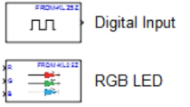
    Now, because I've mentioned that the S32K3 toolbox uses an external configuration tool for setting the pins, clocks, and peripherals, let me show you how this tool affects the typical workflow. As before, to add a new block into our model, we have to open the Simulink Library Browser. We can see the main categories of the S32K library in the area shaded in blue. Let's use the digital input-output block from the I/O Blocks category. Simply, we drag and drop this block into our new model.

    If we open this block, we can find two selections here. The first one is function. Here we can choose between all the available standard AUTOSAR functions for the selected MCAL component-- in our case, the DIO. The next option is a parameter required by the previously selected function. And of course, it is different for other functions or MCAL components. In this case, it's the channel ID. The options displayed here are channels configured in a default configuration project automatically associated with this model.

    For the default project, these are the signals configured for the S32K evaluation board like switch forward. On the next tab, we can see the configuration parameters for the DIO component. If we are pleased with the settings from these dropdown menus, we can press the Build button, and the application will end up running on the S32K evaluation board. We call this workflow basic user mode.

    But let's assume we want to add another switch on a different pin. Let's open any block again. And you may have already noticed that there are two extra buttons at the bottom of the block's mask. If you want to change the default configuration settings for this model, we shall press the Configure button. This will launch the External Configuration Tools where we can modify the settings for the pins, clocks, and peripherals according to our requirements. We can use either the NXP's S32 Configuration Tools delivered with our Toolbox Installer, or we can use ElectroBeats Tresos Studio.

    Once we are happy with all the changes, we save and close the Configuration Tool project. Back in our Simulink block, we shall press the Refresh button. This section will read the new configuration settings and repopulate the options in dropdowns. To choose which of the external configuration tool to be used for the Simulink model, we open the Simulink Model Hardware Settings, and under Configuration Tool, we select the desired one.

    Typically, when we develop an application in Simulink to eventually run on an external target, we start by creating the model for simulation and work our way up, reaching the hardware after a few steps. To make sure that this model matches all the requirements and passes all the test cases, we can evaluate the controller model at every step in its way from the simulation to the actual hardware. The first step would be modeling the loop. Here, we take the Simulink model of our application, and we connect its inputs and outputs to a plant model. This one feeds our controller model with some test vectors, so it drives our controller model through different scenarios.

    The next step would be software-in-the-loop. Here, we start to generate C code from the Simulink model using the embedded coder. To test the generated code under the same scenarios, we have to compile the generated code and feed the object file with the same test vectors. Even if both MIL and SIL are executed on the PC, software-in-the-loop can tell us if the controller model can be converted into C code and if the generated code returns the same results as the native Simulink simulation outputs.

    To test the generated code directly on the board and check the correctness of the results together with the processor performance, we have to go to the next step, the processor-in-the-loop. The difference between SIL and PIL is that in PIL mode, we are using a cross-compiler to build the generated code into an object file able to be executed by the target MCU. The advantage of PIL is that we can use any evaluation board to test our application performance on an embedded target long before we have the final hardware design.

    In our case, we can connect the algorithm running on the board with the plant model running on the PC via serial connection. During the simulation, the host application fits the algorithm running on the S32K evaluation board with data, requests the results, and can also profile the application performance. In the end, we can use Simulink Simulation Data Inspector to compare the results. Let me show you all the settings on a real model.

    To guide you through the process of migrating a Simulink model to be executed in PIL on the S32K3 44MCU, I choose a very simple controller which returns the product of two input numbers. The plant model provides the inputs to our controller, which has been set as a reference model, and compares the results in this scope. For the input tables, I've generated some random arrays using a MATLAB script. To select our target, we go to Model Settings, Hardware Implementation, and select the NXP S32K3x hardware board.

    Now let's expand the Target Hardware Resources. Under User Paths, we can change the configuration tool. S32K Config tool comes with the toolbox. Let's choose this one. And let's go to PL. And here, we have to select the LPUART instance on the board. On the evaluation board, it's LPUART 13. And for the COM port, we have to check the COM number assigned for our board. But let's first connect the board to our PC.

    The first USB is the integrated debugger. The second one is the USB-2 serial converter. Finally, we connect the 12-volts power supply, and we power on the port by the switch. Now, we can either check in Device Manager, or in MATLAB, we can type serial port list command. And there are two because we are using dual USB-to-serial converter. And because the LPUARP 13 pins are connected to the channel B, we are going to select the COM 43. So let me go and type COM 43 here. And that's pretty much it.

    Now, in order to have a successful PIL run on our setup, we have to set the same settings as for the plant for the reference model. And here, we can either go and redo all the steps, or we can go to Model Explorer, save the plant. And we can use this configuration as a configuration reference for the controller as well. So first, we have to convert to a configuration reference. And let me rename this as S32K344 PIL. We can save it as an external file as well.

    And now we can go and propagate to our reference model. In our case, it's the controller. So let's press Propagate, Yes. And now the configuration for the plant has been also transferred to the controller. So let's save all the models.

    Now let's go to SIL PIL Manager. The system under test will be the model blocks in SIL PIL Mode. And we can run only one reference model on the target. Here, we have three options-- automated verification, simulation only, which is a model in the loop, and the third option will execute only SIL or PIL. Let's start with modeling the loop first.

    And in the scope, we can see both results and difference being 0. To select SIL or PIL, we have to go to Block Parameter Subsystem and select the simulation mode. Let's test SIL first as automated verification. We can now see that the simulation is ready, so the SIL code generation starts. But I will fast forward the process. This is the Simulink Data Inspector. And what we can see here is the automatically generated comparison between MIL and SIL results. But of course, it looks the same with our scope. Also, we have the Code Execution Profiling Report.

    Let's go back and select Build and run the automated verification for this case too. Once again, I will fast forward the process. Now, on the right-hand side of the screen, we can see the board during the flashing process, and the message appear on the screen that the executable has been downloaded on the S32K344. Again, we can see the results comparison between MIL and PIL results, or we can create a custom report. The profiler results are also here.

    I hope that this setup tutorial was useful for you. If you want to find out more about the NXP model-based design toolboxes, please check our Beginner's Guide or our online training courses. Also, if you have questions and you want to discuss directly with the NXP engineers who are developing the toolboxes, feel free to ask any questions on the Model-Based Design Community page. Thank you very much for your attention. Javier, back to you.

    Thank you, Marius. Great to see all the improvements NXP has introduced. Now it is time to generate code from our neural network and download the code onto the board. In preparation for this, I downloaded and installed NXP's model-based design toolbox for S32K3. This is the open loop model that we will use first. The model referenced at the center contains both SOC estimation methods, the EKF and the neural network. We will keep them both for comparison.

    The neural net is implemented with a predict block from the Deep Learning Signaling Library. The only parameter to be specified is the name of the neural network object from the training phase, which must be available in the MATLAB workspace. The EKF is set to represent the behavior of the 0-th order equivalent circuit.

    Here's how we configure the model for PIL simulation. Let's open the Model Configuration dialog. First, we go to Hardware Implementation and choose the NXP S32K3 port. Then we go to Hardware Board Settings and select PIL. Here, we configure the ports that Simulink will use to talk to the board on serial interface. In my computer, the universal asynchronous receiver transmitter is set to LPUART13, and the communication port is number 5. We should now be ready to generate code and download it into the board.

    From the tool strip in the SIL/PIL section, we can select whether to run both desktop simulation and PIL or PIL only. We will do the latter. Once the code is downloaded into the board, I receive a notification, and then the model starts running. We can see that the SOC prediction is very close to the true SOC, and its accuracy is comparable to that of the EKF. At the end of the simulation, we can read a profiling report with performance statistics and examine execution times, number of function calls, et cetera.

    Our next example illustrates the PIL execution mode, but this time utilizing a much larger and more realistic battery model, one that includes both plant and controller in closed loop. On the left, we have all the VMS algorithms. Looking inside the SOC estimation subsystem, we enter the FNN block. And here we have the neural net subsystem on the right that receives the five signals it needs to perform its prediction. In this case, these signals do not originate from the workspace as in the previous example, but they rather come from the plant model sensors.

    Observing the neural net subsystem in detail, we realize that this is indeed a variance subsystem, meaning that it contains more than one version of a certain functionality. In this case, it contains both the original neural net trained in MATLAB that we discussed last time and the TensorFlow imported neural net that I just described. Normalization and moving averages are implemented with MATLAB functions or native signaling blocks. As usual, we include the EKF estimation for comparison.

    Now we will see the battery pack that we are modeling. Again, with varying subsystems, we can switch among the various planned configurations. Let's use the smallest since it is the one which will simulate the fastest. We are managing a 6S1P module whose unit cell has been parameterized according to the characterization of the LG battery cell whose data was used for the neural net training.

    Again, we configure the model for PIL simulation like we did before. Then we run a desktop simulation to check for any inconsistency. Finally, we run processor-in-the-loop. Code is generated and downloaded onto the board. And when the simulation ends, we can evaluate its performance with a profiler.

    And with this final example, we conclude our discussion. Let's review what we saw today. This webinar described the co-generation and PIL implementation of a neural net-based SOC estimation method on NXP hardware. We started with a review of the importance of SOC estimation as part of the BMS tasks, then we discussed the option of using AI workflows for SOC estimation and what their potential benefits could be with respect to traditional methods.

    In the third place, we showed that MATLAB can import a neural net trained outside of the matrix ecosystem. In this case, we imported and F&N trained in TensorFlow. Then we introduced the NXP Model-Based Design Toolbox for S32K3. Next, we used Simulink blocks from the Deep Learning Toolbox to implement the neural network functionality into Simulink models, a simple open-loop model, and a closed-loop VMS model. And finally, we used the NXP MBC Toolbox to generate embeddable code from the neural net and ran both Simulink models in PIL mode, showcasing cogeneration and the option to create a profiling report to assist build simulation performance.

    On behalf of MathWorks and NXP, we hope this event has been a good use of your time. We thank you very much for your kind attention and look forward to talking to you all again soon. Thank you, Marius, and thank you, all.

    View more related videos