FPGA, ASIC, and SoC Development with MATLAB and Simulink - MATLAB & Simulink
Video Player is loading.
Current Time 0:00
Duration 37:36
Loaded: 0.44%
Stream Type LIVE
Remaining Time 37:36
 
1x
  • Chapters
  • descriptions off, selected
  • en (Main), selected
    Video length is 37:36

    FPGA, ASIC, and SoC Development with MATLAB and Simulink

    Watch an overview of ways your projects can benefit by connecting MATLAB® and Simulink® to FPGA, ASIC, and SoC development. Learn about the variety of ways that customers can improve their productivity or even target FPGA hardware for the first time.

    Highlights include:

    • Challenges of FPGA, SoC, and ASIC design verification
    • Importance of collaboration between algorithm developers and hardware design and verification teams
    • Exploration of hardware and SoC architectures and how to automatically generate HDL code
    • Algorithm-level hardware design IP for wireless, vision, radar, and AI applications
    • Techniques to reuse MATLAB and Simulink to speed up RTL verification

    Published: 13 Jul 2022

    OK, welcome, everyone. So MATLAB and Simulink have been used for decades by engineers developing algorithms that end up in embedded systems. With the power of FPGAs, A6, and heterogeneous devices like programmable SOCs, engineers have been looking increasingly for ways to be able to get those algorithms running on these high performance devices. So I'm Eric Cigan. I'm the principal product marketing manager here at MathWorks for our HTL products. And today, I'd like to talk to you about how a family of our products can help engineering teams like yours work more collaboratively to get designs completed more quickly with high levels of quality and may even make your work more gratifying.

    So let me make my points here by covering several subjects. So first off, I will highlight the sorts of challenges specific to designing for hardware implementation as well as verifying those implementations against specs. Then, I'll cover issues that arise when design teams try to incorporate new algorithms in hardware and the value of collaboration between algorithm developers and the hardware teams overall. We'll use an example design to show how some of the design tools we have can help in exploring hardware and SoC architectures using simulation followed up with automatic code generation for VHDL and Verilog

    And we'll quickly look at how high level IP fits in and how integration with popular workflows can help you design for a variety of applications. And finally, since design is pretty worthless unless it's been verified, we'll cover how you can reuse the work you've done in MATLAB and Simulink to build your test environment. This introductory level webinar is actually the first in a series the MathWorks is delivering to engineers here looking at the area of FPGAs and SoC's. So later on, I'll provide some pointers to some upcoming webinars that are also in the series.

    Now important thing that I think all of us know is that most of the content of a new FPGA or ASIC design probably came from a previous one. It could be also from acquired IP that came from other sources, whether that be the FPGA vendor or just wherever you are in the ASIC space. Now where problems can arise most definitively is when there's new content, where there's new algorithms that you need to implement in hardware.

    Then you have system designers or algorithm developers-- let's call them that-- using MATLAB and Simulink to develop this new content. But then they often are separated from their hardware design teams by the organization. And it's this siloing among the different participants in design that can really help contribute to some of the problems that we see over and over again.

    For instance, to prototype a new algorithm, an algorithm developer will write specs, meet with hardware teams to convey that new content. But this can take time as a hardware developer has to work through how to architect the design, how to transform a nice floating point design in MATLAB or Simulink into a fixed point design implementation for efficiency. This can take weeks or more for the hardware team to work through this and have a prototype or implementations ready to go on the development board.

    So the challenge is compound when you're taking that new content into production where there is much more to be done to make sure that this new content performs correctly under all expected operating conditions. So this is where design verification takes on a huge importance. Surveys done over the years by companies like Mentor Graphics which is, of course, now Siemens EDA, these consistently show the verification can be the largest single element in an overall design project.

    So the fundamental problems are just the types of miscommunication can occur when written specs are the means of transmitting all this information because specs-- there's always gaps in those. How gaps are addressed might depend on the downstream team and the assumptions they might make. It's also inherent that working in different environments with algorithm developers in a high level language like MATLAB or Simulink, hardware designers working in their traditional HTL environment. Working those environments actually makes it harder to evaluate different approaches or hardware architectures.

    Also, just the sheer matter of writing of VHDL or Verilog. There's a real possibility of introducing errors with newly written code. And it really locks you into that design once it's written. And finally, just the whole aspect of cross-team iteration.

    When you're working on a new algorithm, you really want to have some close communication between the originator of that algorithm and the one who's implementing it. And you're going to certainly introduce delay into your whole process of design if you have this big macro loop around the whole workflow.

    So what we're proposing, though, in contrast is working collaboratively in a high level environment at a higher level of abstraction. The nice thing you see within this collaboration is the different teams, algorithm development, hardware design, verification engineering can really look at this high-level edit design before you've rendered it down into HDL.

    You also get the ability to look at the overall context of the design instead of just focusing on the part that's being implemented. You can look at how it behaves as part of a radar system. Also if it interacts with other real world hardware, you get the ability to use simulation models to represent that and evaluate the entire system's behavior at a systems level.

    Also having the ability to generate really high quality RTL Viralog and VHDL, as well as verification models really is a great way to reuse what you designed at the highest level at the specification level. And finally, if you're especially if you're going to prototyping, or you're in a prototyping phase, having the ability to relatively quickly go and target specific popular boards from AMD Xilinx, Intel, microchip, that's a very, very powerful proposition to save time.

    All right, so let's-- I've been freely throwing around MATLAB and Simulink here interchangeably almost. But it is important to note that both of these tools are used in development of high-level algorithms. We tend to see MATLAB used a lot in areas like signal processing, communications, even vision applications.

    It's great handling these large data sets. It's really concise, compact language. And it's really tied closely to all the visualization you could do in MATLAB.

    Similarly, on the other hand, it's really great representing parallelism. It's really hard to necessarily do that in MATLAB. It also has an explicit notion of timing whereas MATLAB is just purely untimed. Part of the beauty of it. But it also means that there's ambiguity potentially there.

    And Simulink is also really good at handling data types as we'll see a little bit more here as we go through this example. And even at that system level context, it gives you the ability to bring in not just digital logic but also just analog behaviors, continuous time behaviors, so you can really look at the overall system context.

    So realistically, what we end up finding is customers often blend the two approaches. But whether you're using one or the other or both these tools, what we're advocating for is this workflow where you start off with a title of specification in MATLAB or Simulink. And then you refine it.

    You first reckon with issues of streaming. We'll talk about each of these up ahead. You'll see having to deal with hardware architectures.

    There are different ways of implementing high level functions and also just dealing with the matter of going from floating point, which is how, by default, MATLAB and Simulink work and go into a fixed point.

    So we're going to go ahead and look at this example. And the very first thing you end up having to face a lot of the time is partitioning out the part of the design that's actually going to be intended for implementation from an overall environment. In this case, you see over here in the middle, this is an example we're going to use for the course of today's webinar. You'll see that this is actually a front pulse detector.

    And one aspect of it is a mashed filter. So here you see we're constructing the filter. We're actually applying the filter to an input stream. It's called RX signal.

    And then within there, we're looking for a peak using the max function. And we're going to look where it is-- where the peak is within this data stream. So that's the very high level description. The algorithm over here is some stimulus.

    It was created to run through that. And then over here, we're looking at the ways we can visualize that or post process the results in a simulation. So before you can really go further, the first thing you need to is partition these things apart because this is going to be some form of environment or even a testbench whereas this is going to become what you would call your design design editor test, or DUT.

    So this is the case with MATLAB. But it could be just as much the case with Simulink. So this is really the first step that you want to get through. The nice thing is, once you've modularized like this, then that same testbench can be applied to different levels of abstraction as we go through the design refinement process, or if you have alternative implementations you want to try out within that same testbench being applied.

    So the first refinement once you've broken out the design itself from the environment is to adapt the algorithm to work on a data stream. So here we have this long stream of all this data. And certainly we could wait for many, many samples to come in before we look for the peak.

    But the more we take in, inherently the more latency, the more delay between acquiring the data and getting a pulse out. More delay goes on. So there's a design element there of how much data are you going to wait for before you do this computation.

    So what we did here in this case is we're using sizes of 11, taking 11 samples, looking for the peak within there, checking it whether it meets a threshold level, and then moving on and chunking through the data in that fashion. So this is typical of the process that you have to do when you're building hardware. And then you can look at really an alternative implementation of that in Simulink.

    So you can see right here clearly Simulink is very visual. You can naturally-- you just can inherently see that data flow going here from left to right. And you can see here that we have data coming in, received data.

    It's passing through a filter. Then, it's going through this computation of power, multiply here, and then proceeding on down. And you can see that we're putting in here this 11 sample delay as we do these local computations here.

    The nice thing is even if you do it in Simulink, you can still use the same MATLAB for the stimulus. You're just passing variables through the workspace of MATLAB. And you can just run the sim command to run a Simulink model from MATLAB. So again, this is just an indication of the kind of hybrid approach that many customers do in using MATLAB and Simulink in combination.

    Now, we've taken two steps. Now we've broken out the design from the environment. We dealt with streaming. Next element would be having to deal with hardware architectures.

    So what we're doing here is we have a whole library of over 300 blocks within Simulink that are HTL ready. So that starts with fairly basic ones, like addition and multiplication that you see kind of built here into this filter. Or it can be at this macro level. In this case, a fur filter.

    And the nice thing about these high level blocks is in many cases, there's multiple architectures that they are based on. So if you're a signal processing engineer, you'll probably quickly recognize these different forms of stock, transposed, or a partially serial systolic form. So depending on whether you're optimizing for minimizing resource usage or trying to minimize latency or other elements, you might want to choose amongst those using your design know-how.

    But these large high level blocks do span a number of applications, signal processing wireless comms, linear algebra, AI deep learning, and vision applications as well. So this is really encouraging design at this sort of high level of abstraction that's closer to the level of specifications that your designing system in response to.

    So that next step once we looked at architectures is reckoning with the fact that these designs coming in are usually in floating point because that's the natural language of MATLAB and Simulink. But they model a fixed point with accuracy and precision, of course.

    So we have really a couple of ways to go about that process. One of them is a manual approach. So here you see a 40 bid number coming in from the left.

    And it goes through this conversion block that limits it down from 40 bits down to 18. Why would you do that? Well, because you may be designing for an FPGA that has limits on the DSP blocks.

    It's optimized for 18-by-18 multiplies. In that case, you might want to limit down to here. So you're using fewer modifiers if that's all the accuracy you need.

    In this case, of course, you come out with a 36-bit number out. And then you can, again, reduce that back down once you've done this addition to actually get 37 bits.

    And that can then be brought back down to 18 bits for a further multiply down the road. So this is just a way this can be done by hand. And you're not just doing that on the fly.

    Simulation is your assistant here. And so you can be logging data as you're trying the different quantizations. And here as we can see, we're able to see the Min max ranges on each value as you go through the design. So if you're really putting in representative data, no matter where you got it from, other simulations. You constructed it artificially or maybe acquired it in from some other source. Now, you can look at the ranges and make engineering decisions of how much precision you want to retain.

    So that's the-- we would call the manual approach, though, it's aided with the use of fixed point designer tool for MathWorks. But we also have a fully automated approach. In this case, you're really simulating the data with representative data into your design. But then the fixed point designer tool assesses the data as it goes through the tool, looks at the ranges, and provides this sort of histogram of that data.

    So the blue meaning sort of the frequency, darkest blue means that's where the most that data lies within a given value. We can see the whole range. And we can see that if we start applying fixed point types, as we have done here, we can see where we have overflows or under flows. There's no overflows reported in this design.

    But you see all this yellowish orange. Those cover under flows. This particular boxed one here, you can see that this is actually a 19-bit number. And that gives us down to the -18. But anything below there is going to just wash out as being an under flow.

    So you could choose as the designer to either accept these proposals that came automatically from a fixed point designer, or you can specify your own. That's up to you. And the nice thing is you can be checking through simulation the performance of this fixed point design against the original spec and floating point.

    Obviously, there's going to be a difference. But it's up to you and your judgment to see whether those differences are within acceptable range or not. So you have the flexibility. But you have some tools to use along the way.

    That all being said, in some cases, you may want to keep floating point. Now, historically, in FPGAs it's been accepted that the designs are going to be done in fixed point because it's much more efficient.

    However, there are times like when you're just trying to prove out an algorithm where you don't want to sweat the details of a fixed point. If it doesn't work in floating point, then why bother going through all the work, right?

    So there have been ways in the past. There have been providers of floating point IP out there that you could use. There's even some FPGAs out there that have been designed in with the IP blocks that can do floating point multiplies directly.

    However, the nature of those solutions is that they lock you in with one particular type of FPGA. And you may not want to-- you may want to preserve your flexibility.

    So in this case, what we're doing is we're looking at this, again, part of the data path. And you can see the 16-bit data coming in. It goes through this filter.

    And you wind up with 40-bit data coming out. I'm not sure why exactly it came out 40. But that's what it was in this case. And then it has to get limited back down.

    Now, what you could do is use within HDL Coder a feature called Native Floating Point. It's a library that applies to many of the blocks here where you can get the full range of single, precision, double precision, or half precision floating point in your computation. So what you're looking at here, same basic design. But in this case, now we've gone from a 16-bit fixed point to a 32-bit single floating point filtering that and then converting it back to an 18-bit number.

    Now, this is part of this pulse detector design I talked about earlier. It may not be the best case for when you would use floating point. But we have lot of customers who do controls applications such as motor control or power electronics control. And it's certainly comms, there's many applications that have feedback.

    And you might want degree of accuracy. We have a lot of radar customers, too. So in those cases, you may want to have that.

    So within HDL Coder, you can see the flexibility to have floating point where you want it and fixed point where you can get by with that. And that kind of, again, mixed design is quite popular. You can see here, this is part of how you set that up. This is one of the windows to configure HDL Coder.

    You can specify the Native Floating Point library. And then you can see here in generate HDL, you're seeing these filter outputs, real and imaginary, coming out to 32 bits

    So we actually make note here of a customer who took advantage of this. Demcon, they make medical devices. It's a European company.

    And they were developing a surgical instrument that would do cutting and drilling. So I'm guessing as a surgeon, you want to have that kind of a tool working very well for you. Well, the nature of that field is there's just a feel that you need to have.

    If you're a surgeon, you're expecting those kind of devices to behave a certain way. So Demcon wanted to, again, give them sort of the best case. This is the best behavior we can out of this algorithm.

    So they generated it through as floating point HDL. Now, and spoiler alert, they end up creating this as a fixed point implementation. So the floating point was 25k. Fixed point was 10k.

    But look and also a 2-to-1 difference here in DSP slices. But the development time for the floating point just a single day, whereas, it took them a week to do the fixed point implementation. So this is the case where they were able to get that feedback from surgeons using the floating point implementation before they went to the trouble of doing the fixed point conversion.

    OK, so now we've gone through these different stages of design. But we haven't talked so much about verification yet. But we've done all these different levels of refinement.

    We find that the best practice is to build a Simulink model. So you've got that same stimulus being applied to both a reference algorithm that is the original specification, MATLAB or Simulink. And then you're applying the same stimulus into the designer test. And then essentially you build in a self checking checker in Simulink in this case.

    So here what we can see is this is actually this pulse detection. So we look at the different outputs here that we're getting as we compare the designer test in the reference algorithm. And also this was developed, this testbench, was developed so that it would provide this textual reports back into the MATLAB window.

    This is a very useful way to set up this kind of a simulation because then it can be done in batch just as easily as interactively. And clearly, if you're going to go to production, you're going to want to be able to run verification checks in batch. So this is a great way to test each of these refinements along the way, not necessarily waiting till the very end but checking each point along the way.

    All right, so once you've verified that your refinements have given you the right results and their within the right specification ranges, now you're ready to generate your RTL in VHDL or Verilog. So our product for that is HDL coder.

    So it accepts MATLAB and Simulink as design sources, as well as this tool called Stateflow that's created a modeling finite state machines. Lets you bring in other existing VHDL Verilog as well. And the code that it generates is very highly readable, traceable.

    And when I say traceable, an example of that is the fact there's tags within the generated HDL code that if you click on those, it will bring you back to a Simulink model. So you can see the correlation between them. And it goes the other way.

    You can probe from-- if you've generated code from Simulink, you can specify a block. And then you can generate, can browse through the code. And you can see the corresponding code.

    So you have this traceability. And if you've connected your requirements into Simulink, you can actually go all the way back to the requirements from which the HDL code was derived if you will. This code it produces, this could be used on virtually any device that uses RTL.

    And again, we talked earlier about fixed point and floating point, native floating point. There's a whole set of optimizations that HDL coder can apply. Many of them are automated. Some of them are manual.

    We actually have a webinar that we did a couple of months ago that covers this in quite a bit of detail. We'll be sending out a link to that as part of the follow up to this webinar. But that webinar is called optimize FPGA in ASIC PED using HDL coder. So you should be able to find it pretty readily on our website.

    So I guess a way to visualize what you can do with co-generation is that depending on the optimizations you apply and the microarchitectures you use, you'll come up with a whole set of potential solutions. Some of those might fall within the acceptable speed and area or resource requirements.

    Some may be outside that. But especially if you have multiple solutions that are within requirements, now you can go back and check for other criteria you might have such as minimizing power. The way to do that is bring down your frequency. So your switching rates are lessened. And you can run it less more power.

    You might be able to get greater precision. Maybe if you're a company that's doing other medical instruments, you want to go for greater precision as your differentiator. So having the ability to look at all these different options at the high level is a core value whereas if you suspect things and gone to VHD or Verilog, you're pretty much locked in. It's going to be very hard to rip that up and start afresh with a whole new approach.

    In that example, that webinar that I talked about a moment ago, they used a case here, which I think applies pretty nicely, which is in, I think, the pulse detector design. At one point, you're checking essentially on the norm, a 2 norm of a vector, or the magnitude of a vector. So essentially you're doing a square root of a sum of squares-- Pythagorean theorem, right? And they're looking at using that as a means of judging different pulses and looking at the magnitude.

    Well, yeah, you'll get the direct magnitude in that case, if you take the square root of the sum of squares. But do you really need to? You don't have to be a PhD in math to know that they're going to be the same ordering whether you're looking at the square root or the square itself. So in that case, if the algorithm developer specified a square root, however, a designer is disconnected from that process, you might still do the square root. But if they're consulting with each other, you don't need to do that. You can just use the square.

    So that's just an example of something you can take into account as you're architecting a solution and finding ways to address it, not just by minimizing-- optimizing your RTL code, but just making good design decisions.

    Again, as I remarked at the beginning, what's the good of that VHDL, or verilog, if you haven't been able to verify it? So a good immediate check is something we have called HDL cosimulation. In that case, you could be taking your algorithm stimulus and your checker, running those in MATLAB or Simulink, but then having your design under test running on an HDL simulator. And that's done through this cosimulation.

    The product we have that does that is called HDL Verifier. And what it does is, really, it just lets you reuse your MATLAB or Simulink test environment, testbench, if you will. It automatically produces all the cosimulation infrastructure you need. It actually creates a little block in Simulink that's called a cosimulation block, which is the way representing the communication between map, the Simulink and the simulator.

    And the nice thing about this approach is it lets you-- if you do have problems in your implementation, it helps you debug those. But it also can help you debug your testbench, because these simulators, many of them have means that you can use to look at how much of the code has been exercised by a testbench. So that's a useful way to look for code coverage within the design.

    We should point out that the simulator support we have we've had for many years, support for ModelSim or Questa, which are both from Siemens CDA, formerly Mentor Graphics. We've been supporting Cadence simulators for years. Currently we support the Xcelium simulator. But what's new recently is we now support cosimulation with the Vivado simulator from AMD-Xilinx. So we've been having a lot of customers say, hey, I have Vivado. I don't necessarily have these other simulators. So we're counting on our customers being interested in trying this out.

    So a step beyond HDL cosimulation, say now you want to look at really how things run on hardware, that's really the ultimate confidence builder. We have a feature we call FPGA-in-the-loop. So here instead of cosimulating with an HDL simulator, you're essentially cosimulating with a development board that has your design programmed onto it via bitstream. It could be generated out of HDL code, or it could be from some other source.

    So again, you're reusing the same simulation environment, same stimulus, and checker. And you're able to run this on real hardware. Now, people always want to know, how fast does this run? Well, it's always going to be design dependent. You are limited by the communication between the computer and the board. For most cases, that's Ethernet. For some, we may only have JTAG support. For a few, we actually have PCI Express support, which will be faster yet.

    And it depends on if there's feedback and other elements. But you may get some good acceleration compared to just running with an HDL simulator. So if you have a very long simulation run in terms of many data points, it might be worth the effort of going through the whole compilation and development of a bitstream in order to do this as compared to cosimulation.

    And we support many popular boards that have FPGAs and SOCs from AMD-Xilinx, Intel, and Microchip. This also includes boards from companies like Avnet and Arrow. And we have the means by which you can do this with not only off-the-shelf boards you would just buy from your distributor. But we also have a way that you can use this with custom boards. And we have some specs on requirements for that are all within the HDL Verifier documentation set.

    Well, again, now, if you're going to that next step of production, your verification engineer is going to be knocking on your door and saying, what can you give me? Because I have no idea how this works beyond the spec that you've handed me.

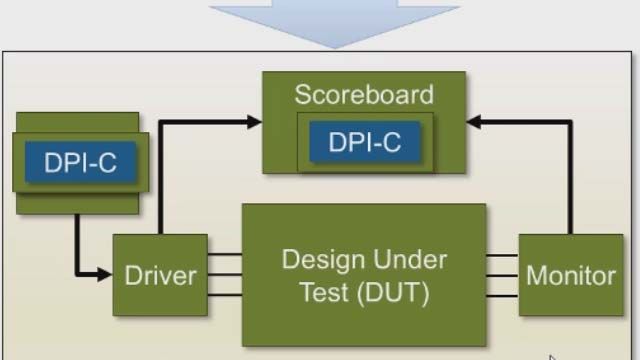
    Well, the nice thing is, again, you can reuse that same infrastructure you've been using all the way along through simulation and design. That is you can generate what we call system verilog DPIC components. That's the direct programming interface, I think. And that's an API that the leading simulators have that lets you bring in components. So it could be something used for a checker, or in this case, it's for the actual stimulus, which you would have.

    So a lot of customers we've found have been really attracted to this. We used to always run into customers at tradeshows saying, yeah, we're doing this design in MATLAB and Simulink, and then we hand code all of our system verilog to produce unit testbenches. And we have to tell them, there's another way that's far more automated.

    So the other thing we've been seeing recently is more of our customers adopting UVM, the Universal Verification Methodology. Some are very far along or a decade into that. Some are just doing it now. And we have an additional capability to not only just generate these system verilog DPI components, but also to produce an entire UVM environment that can help bootstrap you with-- if you're adopting UVM in your newer designs.

    So the one other point I want to touch on here was application specific solutions. So as we talked about earlier on, we have been driven by many of our customers over the years since we introduced HDL Coder in 2006. We've been driven to produce more and more of this high level content. So that tends to focus around applications. So in wireless, there's a whole set of standards that we have developed blocks to support, areas that control, which is Simulink has been used for that ever since it was introduced in the 1990s.

    We have models for that-- blocks, examples that we ship, and so for radar, vision, and even AI. So these application solutions include libraries. They include interfaces. They include examples. And these are based on many cases on our collaboration with our partners in the FPGA hardware spaces.

    So just to wrap it all up here, to start off, we developed these products for the purposes of fostering collaboration between algorithm developers, hardware designers, verification engineers, analog designers, the rest of the design team, software engineers, everybody who contributes into building these end products. So the idea is to get away from solely relying on written specs by complementing those specs with an environment that makes this collaboration more possible. And generating HDL that's target independent, free of errors, and doing so repeatedly is an approach that's let our customers to shave days, weeks, months off of their conventional development processes.

    For verification, we touched on-- talked about at the end, the most popular word out there is reuse. So by all means, we want to help you reuse your testbenches, reuse your test environments all the way through design. We have some customers even going into production and using the data out of Simulink to help them out with their production test environment.

    And this quote here from Marcel at Phillips Healthcare just makes that point very clearly that they found there that Simulink provides this environment where their architects and hardware design teams could communicate and collaborate. And it is a shared language for exchanging know-how.

    So as I mentioned earlier on, we have this series of webinars that we're delivering. So we hope you can join us in these. That URL on top will help you get to the invitations for each of these upcoming ones. Down at the bottom there, you have a link to one of our pages here. And that will really direct you to all our solutions in this space.

    And another thing I should mention here before I break away here, the tutorial that I mentioned and that we used as the example throughout much of this video, look up "Tutorial MATLAB HDL Coder." Put those into a search engine, and you should come up with that tutorial. It's in our community part of our site. It covers everything we've done here and more. So I really encourage you to check that out, because that's really a good study guide to go along with this. Whether or not you're doing an eval, it really gives you a very clear illustration of how these methods all come into play.

    I do encourage you to attend these upcoming webinars. Each one of them is going to be delivered by one of our application engineers here in North America who's an expert in their given area. In radar design, a guy who worked for years with the Air Force Research Labs. Functional verification, the guy who used to be an ASIC verification engineer before joining us, a real expert in vision applications, and then a really sharp guy doing the comms area. And then we've got motor and power coming in the fall. So lots and lots to see and learn here.

    Thanks again for listening today. Thanks for coming today. I encourage you to go and check out some of these sites and to see these upcoming webinars.