Generate Floating-Point HDL for FPGA and ASIC Hardware
Quantizing floating-point algorithms to fixed-point for efficient FPGA or ASIC implementation requires many steps and numerical considerations. Converging on the right balance between arithmetic precision and hardware resource usage is an iterative process between algorithm and hardware design. The process becomes more difficult when it requires a high-precision or high-dynamic range.
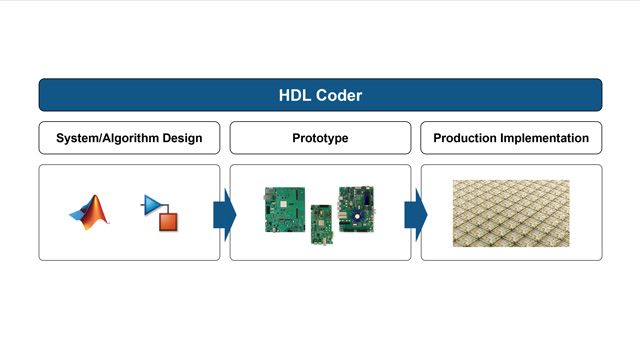
To simplify this process, HDL Coder™ can generate target-independent synthesizable VHDL® or Verilog® from single-, double-, or half-precision floating-point algorithms for FPGA or ASIC deployment. This overview shows how to generate floating-point FPGA and ASIC hardware, including:
- How to identify algorithms that might benefit from staying in floating-point
- What types of operations HDL Coder native floating-point code generation supports
- How to mix fixed- and floating-point implementation in the same design using Fixed-Point Designer™
- How to control latency and sharing optimizations for native floating-point code generation to meet your FPGA or ASIC implementation goals
Published: 1 Nov 2016
HDL Coder deploys your Simulink and MATLAB algorithms to FPGA or ASIC hardware. While most of these algorithms start off in floating point, quantizing to fixed-point can greatly reduce hardware resource usage and operations require fewer steps. But converting all your data and operations to the smallest fixed-point word lengths while maintaining enough accuracy can be very time-consuming and iterative.
Fixed-Point Designer provides guidance automation and visual feedback to help you manage this process. But there are many designs or parts of designs that have numerical requirements that make fixed-point conversion extremely challenging. We see this a lot with motor and power control, radar, and certain wireless algorithms. In fact, one of our power control customers was trying to implement this simple math function as part of their design targeting an FPGA. But this function has a high dynamic range. Depending on the input, sometimes the results require a lot of bits on one side of the radix point, and others require a lot of bits on the other side. So it's difficult to fix a word length and radix point without throwing a lot of bits at the problem.
To implement this in hardware, our customer began the fixed-point conversion process, which required some adaptations. For one, they had to break the divide operation into a reciprocal and multiplier in order to have finer control over the fixed-point word length. And you can see all the manual data type conversion and propagation. And they also had to experiment with a lookup table or a Newton-Raphson in architecture for that reciprocal operation.
So even for a simple math function, converting to fixed-point is not straightforward if the math has a large dynamic range. But what if there was a way to build hardware without having to go through all this? In this field-oriented controller design, there are some operations like we previously saw that it would be nice if we could just stay in floating point-- for instance, algorithms with large or unknown dynamic ranges like integrators and feedback loops, or the saturation block here that had to be added to prevent overflow, or operations that are difficult to design in fixed-point, like an atan2 and other trigonometric functions that typically are implemented in hardware as lookup tables.
Now models like this can be taken directly from floating point to synthesizable HDL code for implementation on any kind of FPGA or ASIC. HDL Coder generates vendor-independent HDL from floating-point models, double, single, or half precision. There's a wide variety of math and trigonometric functions to choose from. And the full range of IEEE 754 features is supported, including dnormal and [? infn. ?]
But how does each decoder actually implement floating point operations using fixed resource hardware? To illustrate using single precision, it starts by converting data to a 32-bit integer, then unpacking the sine exponent and mantissa bits according to the IEEE spec. Once it has split the data into those components, it uses them to perform the arithmetic operations, which, of course, are different algorithms than their fixed-point counterparts.
So in the generated HDL, the inputs and outputs will be 32 bits wide, and floating point math algorithms require more steps than fixed-point. Therefore, in cases where you can use smaller word length fixed-point types, your hardware will be more efficient than staying with float. But for cases where you need a large dynamic range, it can be easier and more efficient to just stay in floating point. You can find the right balance for your design by mixing fixed and floating point operations. Let's look at an example.
Here in the field-oriented controller design, you'll notice that the data types are all single precision floating point. To generate negative floating point HDL, go to the Floating Point Target setting and choose the target. You can map to FPGA vendor macro libraries, but you won't be able to see or trace into them. Native Floating Point will generate target-independent code that's completely readable and traceable.
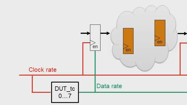
There are some customization options here. Let's focus on latency. Remember, floating point math has some extra steps, and this extra logic takes time for data to propagate through it. If you were manually writing RTL, you would shorten these paths by inserting registers. It makes it easier to synchronize signals from converging paths, and shorter paths mean you can run at a faster clock rate.
HDL Coder provides some options here. For instance, you could try zero latency, in which case you would add some really long paths, forcing you to use a slow clock rate. If you try one of the other choices, you have to set the oversampling factor because you don't want to insert registers at the design sample rate that would increase latency through the design. For more on this, I encourage you to check out this video.
For this design, the sampling rate for the inputs and outputs is 20 kilohertz. By setting an oversampling factor of 800, that assumes we can run the FPGA at 40 megahertz, and any inserted registers will also run at that clock rate. The default setting here is MIN latency, which provides a nice balance. If you want to see the min and max for each operator, they're all listed here in the documentation. And if you want even more control, you have the ability to set this for individual blocks, and you could even specify a custom latency value.
Moving to the Optimization settings and looking at the Resource Sharing tab, there is an option there to share floating point operators. It's on by default because all optimizations are supported as part of native floating point. The first example here is resource sharing. This is a simple example of two floating point sign operations, and with resource sharing enabled, they can be time multiplexed so one fixed resource can be shared for both operations.
Even more powerful is algorithmic-level sharing. Take the case of a sine and cosine operation. The underlying argument reduction computation can be reused between both. Designing the hardware at the algorithm level provides more opportunities for high-impact optimizations like this. And if you're going to generate a test bench as part of the HDL coder run, there is an option to specify error checking to use relative units in last place so the test bench will ignore small bit errors in the least significant bit of the mantissa.
The Code Generation Report will have a native floating point section of the resource usage report, which shows the resources specifically used for floating point operations. As expected, there's some overhead for using floating point operations because they require more steps. In the generated model that HDL Coder produces, visualizing the sample rates shows where the 800x oversampling was applied. Looking into the code, the inputs and outputs are 32 bits, as expected, and those signals get split into the sine exponent and mantissa components. And these delay signals are pipeline registers that were added to shorten the paths through the extra steps in the floating point calculations.
Now, if I want to reduce resource usage, I can combine fixed and floating point in the same design. Here I've converted the same design to mostly 16-bit fixed-point using Fixed-Point Designer. But I've isolated and used floating point for the sine cosine operation, whereas in a pure fixed-point version, I had to create a lookup table for the sine cosine and use a multiplier on the input to normalize it. And the same for the feedback loop in the current control blocks, because small errors could become really magnified. Note that using floating point also allowed me to remove the saturation logic.
After HDL code generation, the improvement in resource usage is pretty clear. And I had set a 50 megahertz target frequency to provide some margin over the real target of 40 megahertz. But after this is done running synthesis, it shows that there is plenty of margin. And it's nice that I could iterate within HDL Coder to get the right balance of resource usage versus precision before running all the way through synthesis.
So with HDL Coder, you have a few options for floating point operations. Native floating point is nice because it provides such broad coverage with good precision and can help you quickly get your design onto real hardware. And there are a lot of options to fine-tune settings for meeting production implementation goals. This has been used for a variety of customer applications, but DEMCON here was kind enough to share details on how they use native floating point to design the controller for a surgical instrument. So check out this user story to learn more.