Simulink Fault Analyzer Essentials, Part 4: Conduct a Fault Sensitivity Study
From the series: Simulink Fault Analyzer Essentials
You can use Simulink Fault Analyzer™ to conduct a fault sensitivity study to analyze how sensitive your fault detection and mitigation logic are when abnormal behavior varies. Learn how to conduct a fault sensitivity study using the Multiple Simulations panel by adding faults to a design study and varying fault behavior across a suite of simulations.
Published: 23 Aug 2023
Hi, everyone. This is Pat from the Simulink Fault Analyzer team. In this video, I'm going to show you how to use Simulated Fault Analyzer to perform a fault sensitivity study. I will be walking through one of our shipping examples, Conduct Fault Sensitivity Study on Warehouse Robot. Feel free to open the example using the link below to follow along.
Let's open the model in Simulink to see what it does. As the visualization shows, the robot is sent along a path between three stations. The model includes a simple safety lock mechanism, which commands the robot to stop if a spin is detected. I have also added a simple assertion to stop simulation. This will come in handy later.
The model includes two faults, both of which will attempt to put the robot into a spin. Let's activate the timed fault and simulate the model. Let's open the simulation Data Inspector to see the results. It looks like the fault was injected as expected. But the safety lock was not activated. What would need to happen in order to induce a spin?
Let's find out by conducting a fault sensitivity study. The goal with a fault sensitivity study is to determine how effective fault detection and mitigation logic are against specific abnormal behavior. In this case, I will be varying the behavior of the fault across several simulations.
First, let's take a quick step back. When I say fault, I am referring to any abnormal behavior you want to simulate. In most cases, you want to override the behavior of a signal during simulation. I like to think of a fault as having three properties. The first is the where, which is the location of the signal you want to override. These are defined as model elements, such as a block in port or out port.
The second property is the what, which is the abnormal behavior you want to inject on the signal. This is modeled in a separate file we call a fault model. The third property is the when. You can inject a fault at the beginning of simulation, after a given simulation time, or based on a system condition. If you combine all three, you have an instance of a fault.
For any given model element, the where, you can have any number of associated faults with their own behavior and trigger settings. However, only one fault per model element could be active during a given simulation. Model elements are enabled. Faults are activated.
Let's go back how to set up a fault sensitivity study. Recall that my goal is to vary the default behavior or the what. To do this, let's open the fault behavior for the timed fault. The behavior is simply a gain applied to the angular velocity. Of the gain has been parameterized using a base workspace variable, which I can vary across simulations.
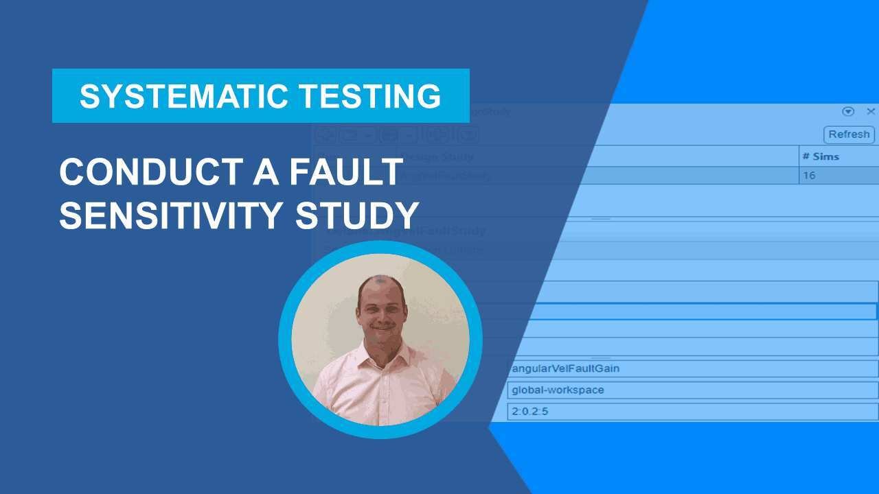
To set up the study, let's open the Multiple Simulations panel by clicking on the Multiple Simulations button in the Fault Analyzer tool strip. The Multiple Simulations panel lets you set up design studies. We can add faults to a design study. Let's first create a design study, which I'll call Angular Velocity Fault Study.
Now let's click on the button with the the Fault icon to add the set of faults associated with the model. The angular velocity timed spin fault is set as the active fault. We also need to add the base workspace variable, angular valve fault gain, to the study. And set its values as an array from 2 to 5 in increments of 0.2. Note that the number of simulations automatically changes to 16.
Before I run the simulation, I want to highlight something I briefly mentioned before-- the assertion in the safety lock mechanism. The purpose of the assertion is to stop the simulation and throw an error. Let's see what this does within a fault sensitivity study.
It looks like the simulation started to error out starting in the fourth simulation. In this case, the base workspace variable was set to 2.6. That is, therefore, the gain required to trigger a spin and activate the safety mechanism.
Where could you go from here? In addition to the fault behavior itself, you can also vary the specific time a fault is triggered. This can be accomplished using the Simulink Fault Analyzer APIs.
Let's review. In this video, I showed you how to set up a fault sensitivity study. This could be useful in stress testing fault detection and fault mitigation logic. Check out the example I used, using the link below, for more information.


Seleccione un país/idioma
Seleccione un país/idioma para obtener contenido traducido, si está disponible, y ver eventos y ofertas de productos y servicios locales. Según su ubicación geográfica, recomendamos que seleccione: United States.
También puede seleccionar uno de estos países/idiomas:
América
- América Latina (Español)
- Canada (English)
- United States (English)
Europa
- Belgium (English)
- Denmark (English)
- Deutschland (Deutsch)
- España (Español)
- Finland (English)
- France (Français)
- Ireland (English)
- Italia (Italiano)
- Luxembourg (English)
- Netherlands (English)
- Norway (English)
- Österreich (Deutsch)
- Portugal (English)
- Sweden (English)
- Switzerland
- United Kingdom (English)