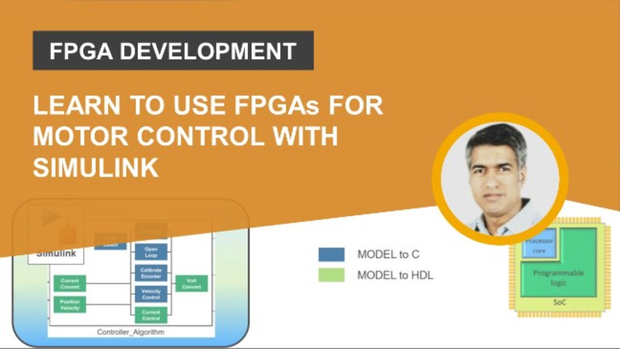
Learn to use FPGAs for Motor Control with Simulink
FPGAs for Motor Control is becoming a pivotal technology in the development of high frequency switching power electronics and motor control systems, driven by highly mathematical computing algorithms. To implement such algorithms, engineers are increasingly looking towards System on Chip (SoC) devices, which blend the familiarity of embedded processors with the capabilities of FPGAs for parallel processing and deterministic behavior.
In this session you will learn how to use Simulink to deploy a field-oriented control (FOC) algorithm, onto an AMD-Xilinx Zynq UltraScale+ SoC device, with minimal need for deep FPGA programming knowledge. Using model-based design we will control a permanent magnet synchronous motor (PMSM), illustrate the process of automatically generating C and HDL code for the ARM Cortex processor and FPGA fabric within the SoC device. The techniques are demonstrated using the Trenz Electronics Motor Control Development kit.
Highlights:
- Model, Simulate, Test and Deploy the FOC algorithm onto Zynq UltraScale+ SoC Device.
- Explore the partition the design for ideal division of tasks between the ARM and FPGA.
- Automate deployment of the algorithm into reference frameworks for the processor and programmable logic.
Recorded: 26 Aug 2021
Hi, everyone. I'm Raghu Sivakumar. I'm part of the technical marketing team at MathWorks, the leading developer of mathematical computing software. I have been at MathWorks for nearly three years, and I work closely with customers, helping them adopt MathWorks solutions for FPGA and SoC devices. In today's talk I'll be covering how, using Simulink, control engineers can deploy motor control algorithms on an FPGA.
The agenda for today's talk, I will first give a brief overview of the topic and what I'll be covering. Next, I will move on to the motivation for this talk and give you an idea as to why this topic is relevant and look at the workflow using a field-oriented control algorithm implemented on a Xilinx Zynq UltraScale+ SoC platform controlling a permanent magnet synchronous machine. We will end today's talk with a Q&A session.
A brief overview of today's talk, I will use a field-oriented control algorithm, model it in Simulink using C and HDL compatible libraries, partition the control algorithm for software and hardware implementations, generate C code and HDL code, deploy the bitstream to the hardware logic, and run the executable model on the ARM processor to operate the model. I'll be using the Xilinx Zynq UltraScale+ SoC platform, which is part of the Trenz Electronic Motor Control Development Kit.
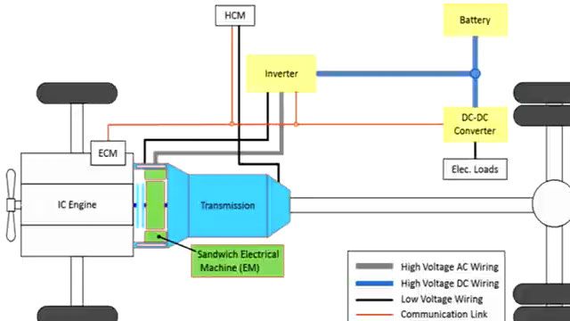
To understand the motivation behind the topic, and to understand why this topic is relevant, I would like to take the example of two customer use cases, Punch Powertrain, a company specializing in innovative electric and hybrid powertrains, and DEMCON, a company that provides services in various industries, such as aero def, agriculture, medical, and life sciences.
Engineers at Punch Powertrain wanted to increase their first-generation electric drive from 10,000 RPM to 20,000 RPM. Design analysis showed that to achieve this requirement, they would have to drive the currents at a rise time of 8,000 amps per millisecond. Implementing such a design on the first-generation microprocessor would lead to errors of over 100 amps. The engineers decided to implement the controller on a Xilinx Zynq SoC. The challenge was that they had minimal FPGA knowledge within the organization.
At DEMCON, engineers were asked to create a surgical drilling and cutting device with significant improvements in efficiency and power consumption, with numerous inputs and outputs to the controller, and a running frequency at 1 megahertz. They decided to use an FPGA-based controller. Their challenge was to get prototypes out in the field, to get direct feedback from surgeons regarding the performance of the device.
Control engineers are facing rapid growth in electrification, adoption of wide bandgap materials, use of precision robots and efficiency improvements to develop highly-complex, fast-switching, compute-heavy digital control systems. To deploy such compute-intensive strategies at high frequencies, engineers are considering the use of System on Chip devices, or SoC. A generic SoC device has a processing system, usually an ARM processor or multiple processors, common memory and communication interfaces, and additionally, programmable FPGA logic that completes the architecture.
Control engineers are familiar with processor architecture and understand the advantage and deterministic behavior of the FPGA, but lack the expertise in HDL programming or complex design tools. Using model-based design enables engineers to use simulation as a platform for evaluating algorithms and hardware. Also, using a single platform for designing the control system improve the design team collaboration. When the design cycle reaches hardware prototyping, MathWorks' advanced auto-code generation tools enables fast prototyping path that includes on-target hardware prototyping.
Using the model-based design workflow, engineers at Punch Powertrain were able to create an integrated drive with four different control strategies. And they achieved this in 1.5 years with two full time engineers. The quote from Rob Reilink from DEMCON highlights that using this workflow, he was able to fully leverage his expertise in designing the controller, and was able to accomplish the project without having to use FPGA engineers. This is what I want to accomplish in today's talk. I want to showcase how control engineers can use their expertise to design control system applications and implement their designs on FPGAs having minimal FPGA programming experience.
Control design engineers commonly used Simulink models early in the development process to gain confidence that their algorithms are functioning correctly. Starting with the conceptual closed loop model of a field-oriented control of a permanent magnet synchronous machine, engineers can use Simulink, Stateflow, and Simscape tools to create the behavior model of the control algorithm and the plant model. In 2020a, MathWorks released Motor Control Blockset as an add-on product for Simulink for designing and implementing motor control algorithms. With this add-on, engineers can use reference examples and Simulink blocks for creating, tuning, and parameterizing field-oriented control and other algorithms for brushless motors.
Fully assembled reference examples are available as a starting point for designing and implementing field-oriented control algorithms for surface mount and interior PMSM induction and brushless DC motor. You can even use these different examples to generate and deploy embedded code. With this top-level system model built, engineers can generate optimized C and C++ or this controller subsystem using MathWorks' embedded quota tool. In this talk, I will show how you can extend this capability and generate HDL code to target the FPGA architecture on the SoC.
To showcase this workflow from design to prototyping, I will be using the Trenz Electronic Motor Control Development Kit. The Trenz electronic hardware is a modular kit consisting of the SoC device module, a carrier board, and the motor driver module. The SoC module is available in two versions. One is the Xilinx Zynq UltraScale+, which is what I will be using for this talk, and the other is a Xilinx Zynq 7020 series. Both these hardware variants are supported by MathWorks. Also included in this is a 24 volt rated, 4,000 RPM, 53-watt brushless DC motor, which includes 1,250 rev counter single-ended encoder. For more information on the Trenz kit, please visit the link provided or Google Trenz Electronic Motor Development Kit.
The field-oriented control is a current controller consisting of two proportional integral current controllers cascaded with an outer control loop of velocity. The mode logic, where mode operations can be selected, and the mode scheduler and the low-rate outer loop that controls the velocity will be run on the embedded processor. The code, consisting of two proportional integral controllers, Clarke, Park, and their respective inverse transforms, convert between the stationary and rotating synchronous frames.
The space vector modulator transforms the phase voltage commands into pulse-width modulation signals, which are applied to the stator windings, is implemented on the FPGA programmable hardware. Using the FPGA for the modulation scheme results in a faster and more responsive BWM switching, as FPGAs can run in the megahertz region. This method enables compute-intensive control algorithms to run on the FPGA hardware, while the supervisory system monitoring and user interface are handled by the processor core.
To implement the model on the FPGA fabric, we will make use of the HDL Coder Simulink library, which has over 250 HDL-optimized blocks. And additionally, HDL generation is also supported when your model designs are built using Simulink library, such as math operation and other commonly-used blocks, such as logic, lookup tables, et cetera. HDL coder can generate target-independent HDL code from native floating point and fixed point data type designs. As of 2021a release, HDL coder supports the following math operation blocks for single precision and double precision code generation, except the math and trigonometry functions. If your design has complex math and trigonometry operations, use native floating point technology.
The top-level Simulink model serves as its system test bench, as in it includes the controller model and a physical model of the motor. With model-based design, we can create a single model having both discrete and continuous time samples and representing both digital and analog systems in one environment. The simulation shows the response of the motor from a dead start. We can see the motor uses less current in the closed loop as the field-oriented control algorithm efficiently operates the motor. We will load the results into the simulation data inspector to compare results from the hardware tests.
To implement the model on the hardware, MathWorks supports many popular hardware boards from Xilinx, Intel, and Microsemi. And to make it easy to set up and configure, hardware support packages are available as add-ons to download. The Xilinx Zynq support package guides you through registering, configuring, and connecting your hardware board. Using the embedded coder support package, along with the HDL coder support package for Xilinx Zynq platform, we can deploy and run the executable on the Xilinx Zynq UltraScale+ platform. This automates the hardware setup, ensuring ethernet connectivity and download of MathWorks firmware image on the SD card.
The hardware-software partition will be the next step. This is a key step in the design workflow, where the decision on which target functions will be implemented on the ARM processor and the FPGA programmable hardware logic. For this model, the outer control loop responsible for velocity control could be performed on the ARM, as well as mode control logic. The current controller and functions processing the controller's input and output requiring faster rates will be implemented on the FPGA.
Grouping the C and HDL components into Simulink subsystems, we will use embedded coder to generate the C code. Embedded coder generates readable C code, which is portable and can be integrated with any embedded processor using ANSI C compiler. For more information on the embedded coder and its capabilities, please refer to the embedded coder product page and numerous resources on the MathWorks website.
Using the HDL coder's workflow advisor, we will generate the HDL IP core. The IP core workflow automates the steps that generate the HDL IP code designed to connect to the embedded processor. The HDL workflow advisor goes over a series of tasks, facilitates the generation of HDL code, and performs synthesis tasks invoking a third-party synthesis tool. In this case, we'll be using a Vivado 2019.1 version as a synthesis tool. HDL coder supports third-party synthesis tools from Intel, Xilinx, and Microsemi.
The generated HDL code needs to connect to the processor on the SoC platform. The HDL IP core generation workflow automatically generates a shareable and reusable IP core from the Simulink model that connects to the processor. To establish the interface and connect to the generated HDL to various peripheral components, such as ADC, PWM, I/O connection, such as I2C SPI on the SoC, we will make use of a reference design framework.
Think of the reference design as a blueprint of the SOC platform, which will be used by the synthesis tool to place the HDL IP core and interface according to our design model. The port's name, port, and data type are automatically populated from the Simulink model. Using the target platform interface dropdown options enables the processor to access the HDL IP core via an advanced extensible interface, or AXI interface to read and write data to and from the IP core.
In task 3.2, we will generate the HDL code. The generated HDL code is highly readable. Hypertext links in the code let you trace back the block in the Simulink model that corresponds to the code. This traceability between generated code and Simulink models improve communication between the design team members, especially when trying to track down a problem. HDL code generation supports both floating point and fixed-point data types. And for initial prototyping and validation, we can use floating point data types.
Using the Fixed-Point Designer tool, you can automate data type conversion to fixed-point if there is need to reduce hardware resource usage and power consumption. The tool gathers the range and coverage of the design and recommends fixed-point data types, keeping the accuracy and maximizing precision. Depending on the project, if high dynamic range calculations are required for certain parts of the system design, you can mix floating and fixed-point operations in the same model. For this capability, HDL Coder was awarded the Embedded Award in 2017.
Embedded system integration task integrates the generated HDL IP core with the embedded processor. The workflow advisor, using embedded coder automates the generation of the drivers that connect to the target hardware, giving read and write capability. Embedded coder generates the AXI address mapping information, which is included in the C header file. The generated FPGA bitstream is then downloaded on the SoC.
In this workflow framework, a Simulink model is auto generated that replaces the HDL subsystem with its equivalent AXI driver block, which enables running the model on the ARM processor as an executable. This capability lets you monitor and tune the algorithm while it runs on the SoC platform. We can see the model go through the same pulse test and upload the test data to the Simulink session to compare it with previous simulation results.
We can see there is a very good agreement between the rotor velocity and phase currents observed in the simulation and those produced in the test. The exception is the first second, where the motor runs in open loop as part of the encoder calibration process. The difference, we see, is because of the initial position of the motor shaft in the model differs from the shaft position in the hardware.
I have showcased how, with minimal FPGA programming knowledge, control engineers using model-based design can implement high-switching, complex control algorithms on FPGA using Simulink. You can design, simulate, and deploy your control system algorithms using one environment. To find out more about the workflow and to get started with the Trenz Electronic Motor Development Kit, visit the following links. Thank you for attending today's talk, and I look forward to answering any questions regarding this topic. Thank you.
Related Products
Learn More
Featured Product
HDL Coder
Up Next:


Related Videos:


Seleccione un país/idioma
Seleccione un país/idioma para obtener contenido traducido, si está disponible, y ver eventos y ofertas de productos y servicios locales. Según su ubicación geográfica, recomendamos que seleccione: United States.
También puede seleccionar uno de estos países/idiomas:
América
- América Latina (Español)
- Canada (English)
- United States (English)
Europa
- Belgium (English)
- Denmark (English)
- Deutschland (Deutsch)
- España (Español)
- Finland (English)
- France (Français)
- Ireland (English)
- Italia (Italiano)
- Luxembourg (English)
- Netherlands (English)
- Norway (English)
- Österreich (Deutsch)
- Portugal (English)
- Sweden (English)
- Switzerland
- United Kingdom (English)