Enabling the Green Hydrogen Supply Chain with MATLAB and Simulink - MATLAB & Simulink
Video Player is loading.
Current Time 0:00
Duration 24:33
Loaded: 0.67%
Stream Type LIVE
Remaining Time 24:33
 
1x
  • Chapters
  • descriptions off, selected
  • en (Main), selected
    Video length is 24:33

    Enabling the Green Hydrogen Supply Chain with MATLAB and Simulink

    Production of green hydrogen relies upon conversion of photovoltaic (sun) and/or eolic (wind) energy into hydrogen gas through electrolysis. This brings multidisciplinary challenges (concept design, planning, operation, maintenance) to guarantee satisfactory return of investment. Now learn how multidomain simulation empowers integration with grid and energy storage, power electronic design, and techno-economic studies.

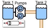
    Once produced, hydrogen must be compressed and transferred from tanks to fuel cells. Electricity is then regenerated for electric propulsion in ships, trucks, or busses. But how can hydrogen, an extremely sensitive gas, be handled safely at all stages? Model-Based Design provides a solid foundation for this. In this session, you will see how safe valve and cooling controls are modeled with Simulink®.

    Finally, it may be that your company is responsible for system integration. Hydrogen-based fuel cells are acquired and integrated in a complex multidomain system and co-exist with other energy entities (e.g., battery, diesel generator). How can you maximize the return for all assets? Can testing be enabled by desktop models used early in the development cycle? Join us to find out how the MathWorks toolchain makes it possible.

    Published: 29 May 2022

    [MUSIC PLAYING]

    Hello, everybody, and welcome to our MATLAB Expo, Enabling the Green Hydrogen Supply Chain with MATLAB and Simulink. My name is Juan Sagarduy. I'm an application engineer in electrification and mechatronics, working in Sweden. Together with me, I have my colleagues, Vasco and Maria.

    Hi, Juan. Nice to be here.

    Nice to be here too.

    Well, right. So we are going to be very active on social media, so a lot of tips, so please check it out whenever you have time. So the structure for the presentation is going to follow an analogy with the hydrogen supply chain. We will start with green hydrogen production from renewables, we will move on to hydrogen distribution, and finally, hydrogen consumption in fuel cells for e-mobility.

    So how is hydrogen producing microgrids? So the example of a wind, and mechanical energy is converted to electrical with a generator. Electricity and water in the electrolyzer will produce hydrogen. And then the energy storage, often the battery, will contribute to that process. Throughout the presentation, we will highlight the value of our multi-domain simulation platform, Simscape, to tackle all challenges when it comes to hydrogen supply.

    Real hydrogen technology is attractive and has many advantages like sustainability, storability, and versatility. However, it poses quite a few challenges due to high energy consumption, safety in managing hazardous hydrogen, and then high costs. We at MATLAB believe that simulation-based engineering will put you on the path to success by reducing risk and giving you added insights.

    So the key takeaways of our presentation today will be how The MathWorks store chain can help you at certain feasibility, techno economic analysis, and proven, giving concepts. Once you have made a decision on the concept, you can secure sustainable and robust operation with design automation and optimization. And then the process of developing technology can be done in a collaborative way, with good sharing of know-how IP and deployment solutions.

    So let's get started with a hydrogen production from renewable to gas. So the challenges for a hydrogen production can be broken down into unit level and system level. So when it comes to unit, we can think about the components, the physical, and controlled. These are related to those electrolyzers, energy storage, power converters, and generators. In the era of digitalization, it's going to be more important to have digital twins that can assist with prognosis development and anomaly detection.

    At the system level perspective, we want to design the plant by choosing the best concept available-- DC versus AC, wind versus solar, and so on. Are the components meeting all requirements, and that at the energy balance is well understood. Now, from an algorithmic perspective at a higher level, so we want to design the intelligence in a good and competent way and then even be able to define the set points in a flexible but accurate manner.

    So going for a model-based design then, some model fidelity is going to be your guiding star. So if you are in the milliseconds or microseconds in the embedded development space, then you are in a different situation than if you want to see system performance from seconds to hours. And then if you are interested in long-term predictions for months and years, then you are in the techno economic analysis space. And then a quasi-steady simulation also call 8760, it will be commonly used. That will recommend a given level of fidelity for the models that you're going to use.

    So let's get started with techno-economic analysis in the solar microgrid. So the easiest way to start this by using components in our Simscape Electrical library for drag and drop use for performance assessment. With some techniques, you can convert those into reduced order models. That will be very agile, and then will empower you for the techno-economic analysis space.

    So the model will look a bit like this. So you can have solar panels, energy storage, and grid with a reduced order model equivalent. Baseload at the electrolyzer model that we're going to use can be applied throughout all the levels of fidelity.

    Very important when using MATLAB that available data from wind, irradiance, or historical electricity prices can be brought in into MATLAB or used in Simulink and Simscape models, thus giving that realism that you need for your analysis. So when you have reduced thermal models, you can run batch simulations with parallel computing or using cloud resources. You end up with agile insights to justify decision making.

    And then in this particular case, you're looking for what is the highest cost and the lowest solar resource when it comes to producing hydrogen. So you could see 242 years simulating 500 seconds. That was quite amazing.

    So now, we will get into medium fidelity and system performance analysis with that little video. So we'll start with the DC generator, when a mechanical energy is converted into electrical, then the energy storage unit with a battery contributing to the production of hydrogen, then supervisory logic, this is what defined the set points for electrolyzer and battery and even switch logic.

    Please bear in mind that we have two regulation modes, voltage versus energy, we will come back to those a bit later on; a DC/DC converters commanded with voltage reference signals; and then a multi-domain representation of the electrolyzer. So with all this, then we are set up to simulate and then visualize for KPIs current voltage, hydrogen produced in kilograms, and the energy consumed in that process.

    So with the voltage-based strategies that we produce 38 kilograms of hydrogen, and then the battery charge will go down to 50%. What happens if we use the energy-based approach? Then we are going to see that the production of hydrogen goes up to 48 kilograms, but then that is at the expense of a higher DC beam current through the generator. See the trace of current, and see that the battery can recharge itself depending on the conditions.

    Some KPIs, like energy per kilogram. So we'll reduce the contribution of the battery, then we are going to lose out on hydrogen produced by 3 kilos, but the battery will retain more charge and then end up with 65%.

    So some wrap up on system performance analysis. So what insights are you looking for? Expected hydrogen production and water consumption. What is the suitable control strategy, depending on the conditions and how close you are to meeting your goal, how intensely you want to use your physical assets.

    Energy storage, what is the size and the expected duty regimes that you aim for, and then all together, simulation results will be instrumental for planning of operations, things like collecting hydrogen, replacing batteries, and maintaining the whole plant will be enabled and thus, have a main impact on manpower and cost when running your plant.

    With these words, I'd like to hand over to my colleague, Maria, who will tackle hydrogen distribution. Take it away, Maria.

    Thanks, Juan. So we will cover hydrogen distribution now. The main challenges that we find when developing the hydrogen distribution systems are mainly what, on the first place, being able to achieve the optimal component sizing, including different domains in the same system.

    We also need to ensure a reliable server operation 24-7, and there are also critical safety requirements that we need to meet, and we have to also provide evidence for this. So we will see how we can cover these challenges in the next slides, and these challenges are also closely related to the ones in consumption that we will also see in a few minutes and will be covered by Vasco.

    So to see how these challenges can be addressed, we will use a case study that consists of a hydrogen refueling station. We have a low pressure supply of hydrogen that taken to 950 bars, and this will be done, thanks to the compressor, in one hour. Then we also have a chiller that when the dispenser is activated, it keeps a low temperature of the gas flow into the vehicle in order to avoid big temperature gradients in the vehicle tank.

    The scenario we want to simulate in the vehicle tank is that we start with an empty tank, and then we start refueling until we reach 6 kilograms of hydrogen at 700 bars in less than 5 minutes. This would be the requirements for the simulation. So now, let's hear how we can model and simulate this.

    What you see here is a model of the hydrogen refueling station in Simscape and Simulink. We have the low-pressure supply, and we have the compressor. The purple line represents the flow of hydrogen that is physically connected between the different components. We have the heat exchanger and the chiller and the high pressure valve.

    This can be coupled with the software, in this case, represented using the Stateflow, and here, we can design the logic, for example, opening the bottle that flows into the chiller, opening the dispenser, among others. If we simulate the model, we can see in this graph the high pressure valve pressure, for example, and we can check if we meet the requirements.

    If we follow a model-based design approach, there are more activities that we can include in the same models such as, for example, control design. We can also manage the requirements we have of the system, and we can create some checks in order to ensure that we are following the right way of modeling. We can also create tests and analyze the coverage. We will see in a second how we can generate code, both see and instructor text. And finally, we can automatically generate reports and ensure that we meet the certification requirements.

    So the software that we just saw can be used to generate code, so you can directly use the logic in a real-time controller using automatic code generation. By doing this, you can reduce coding time and errors and get the source code that is hardware independent. And everything is capturing just one model.

    You can generate both structured texts, texts for PLC and also C code. And you can bring it into the proper IDs and apply it into many different PLCs, ECUs, or even custom hardware. We support other relevant PLCs worldwide, however, this can be a complex implementation, so don't hesitate to contact your MathWorks representative, and we can help you to see how we can implement this process.

    As I mentioned before, we can also cover the part of certification, so to ensure that you meet all the critical system requirements. This we support many industries, such as automotive, aerospace, and there are also some trainings and consulting part that you can use in order to support this process.

    So finally, going back to the challenges we saw at the beginning, we've seen how we can cover these challenges. So for the optimal component sizing, we've seen that we can use multi-domain simulation platform, including physical models, the software part, the logic part. And then we can also include more elements such as control design, requirements tests, et cetera.

    We saw how we can ensure this reliable server operation also, by doing simulations, developing a supervisory logic. You're seeing also a state-of-the-art V&V capability, and finally, for the part of critical safety requirements, we've seen that you've seen a model-based design approach, streamline certification of their embedded systems.

    So now, I'll hand it down to Vasco, and we'll continue with the--

    --presentation. Yeah. Thank you, Maria. Let's now talk about the final stage of the hydrogen supply chain. Hydrogen can be used for transportation and in various industries such as steel manufacturing, but today, we will be focusing on e-mobility and fuel cells.

    The typical challenges presented by Maria are still valid because you need to bring hydrogen from the tank to a fuel cell, but they are some additional one in this when you're integrating fuel cell in a larger system, such as choosing the right model accuracy for a component level versus system level simulation, how to define your optimal system level architecture, and how to use simulation to reduce expensive physical prototype testing phase where you don't want to waste hydrogen in useless tests.

    The fuel cell system exists within a balance of plant. For fuel cell developer, it's very important to have these high-fidelity models so they can prototype and fine tune all the different control strategy for the balance of plants and all of these components. One key requirement for this accurate simulation is the ability to model and integrate multiple physical domains, such as electrical or multi-species gas domain.

    Of particular interest for fuel cell is a four-species scarce domain comprised of nitrogen, oxygen, hydrogen, and water vapor so that you can capture physical phenomena such as the nitrogen accumulation in the membrane of your fuel cell.

    This is an impact on your control software because you need to control a purging valve in the anode so that you can take out nitrogen. So for this reason, in Release 2022a, we added a new PM fuel cell shipping demo within Simscape fluid, so that you can get started with your high-fidelity simulation.

    And if you are here, but not caring about fuel cell, but for electrolyzer, we got you covered because as well in Release 2022a, we have added a high-fidelity model based on the same principle for electrolyzer as well. You can try it out with the comment below.

    But let's go back to the high-fidelity model of the fuel cell, and let's see it in action. You'll find all the typical components of a balance of plant, such as humidifier, tank sources, compressor, and so on. But we have added a new custom domain developed Simscape language that can capture the behavior of four different gas species into the fuel cells. This allows you to track specific quantities, such as the nitrogen diffusion on the membrane that you need to purge periodically.

    Once we simulate this model, we are logging all the tiny little detail of the different component so that we can retrieve things such as the power produced and consumed by the different component, the heat dissipated that needs to be taken out by the cooling system we implemented in the model that allows you to create a chart for thermal efficiency as well as take a really exact look on how your reactor utilization is done in the process, such as nitrogen and oxygen.

    Here we can see in the membrane with the yellow line, we are purging we are opening the valve, and a concentration of nitrogen, the blue one, is dropping dramatically, while the concentration of hydrogen is increasing. This causes some losses that we can capture, so that we can get a really global look on the efficiency of our system.

    But the fuel cell system exists, not only as a part of a balance of plants, usually it must be integrated in some kind of vehicle-- a car, a truck, a plane, or a ship. And if you are buying fuel cell system to be integrated, you need to carry out the fuel cell PAs with all the other components, such as battery, electric motor, the driver, and so on.

    You are writing software that is a higher level of abstraction logic, such as energy management system in order to distribute the load and the currents between the various components such as battery and fuel cell. In this case, you may not need a high-fidelity model that, as we all know, comes with a cost, which is a longer computational time to simulate. So in our solution, you can flexibly choose the level of fidelity, and you can model what you need when you need it.

    You can start with a very basic block, which gives you a voltage versus current curve behavior. If you have data from higher fidelity model, you want to have a faster running model. You can create lookup tables, statistical model using model calibrations workflow. And if you want to integrate fuel cell, but you don't care about the gas dynamics only about the electrical and overall response dynamic, we provide in Simscape electrical, a fuel cell block that you can use for such studies.

    Let's see it in action integrated and electrical powertrain. On the left-hand side, we have the cooling circuit. The battery is presented in orange, the fuel cell in blue. We have the DC-DC converter and then the motor drive on the right.

    On the top, we can see the supervisory logic that needs to implement the energy management system I mentioned before. What we did in this system is that the blocks itself, the battery block, like the one in the orange, can be parameterized on the amount of number of battery pack you have in parallel. So if we scroll down, we can see that we offer the possibility as well to program blocks in that way that you can configure the number of parallel modules.

    The same can be done for the fuel cell so that you can decide how many stacks are going to be active at the same time in parallel. So it's another thing that you can parameterize. You can then write MATLAB scripts in which are changing all these parameters so that you can evaluate multiple architecture with simulation.

    The DC/DC converter is implemented on average. The DC/DC converter and the load are basic three big electric motor performing some kind of load profile. The supervisory logic comprised of a loop to manage the propulsion and the split of the different energy mode between fuel cell and battery, as well as the two thermal. This model is available for download from the file section in this talk, so feel free to check it out.

    One typical result of such simulation could be the architecture and evaluation of your powertrain, for instance, if you're comparing three versus battery model versus two battery model with higher fuel cell, like in the orange configuration, we can see on the chart that the orange dotted line is the fuel cell. It starts working much sooner than the blue fuel cells. So you can go based on this KPI what's better for your application.

    That such model are used very often in hardware-in-the-loop setup, where you both generate code from your control logic like Maria showed. You put it on the device under test the electronics. And at the same time, you take the physical model you use the same code generation capabilities to download it on a real-time system such as Speedcode.

    There, you can manage the interfaces so that you can emulate sensor signal and digital protocols. And if you're interested in taking a deeper look now how a work load works for hardware in the loop, I invite you to register to tomorrow's session for hardware-in-the-loop testing for balance of plant controller for fuel cell system. You can use the link or the QR code below that you find in the slides.

    So we analyzed the different challenges. We provide a flexible modeling and simulation platform that can scale up and down, which our accuracy needs. This can be used to perform trade-off analysis, a Monte Carlo simulation. And you can reduce the amount of time spent on physical prototype testing by enabling hardware-in-the-loop workflows.

    We come now to the last part of our talk. First, this methodology has been applied in industry, particularly, we had this talk last year by Expo from Nuvera, Hydrogen is the New Diesel, where they confirm that using modeling a real-time simulation was critical to iterate the design quickly and reduce the risk of commissioning.

    But when you work within our supply chain, there need to be some kind of collaborative engineering environment. We know the IP protection is a hot topic when exchanging model on the supply chain, and we provide technology such as modern reference or p coding of MATLAB script and Simscape language so that you can protect your IP. If you prefer, you can package your simulation in standalone hubs that can be deployed locally or even over the web so that the customer can have an active simulation of your system instead of a static data sheet.

    Things can be packaged to be implemented in larger system, a shared library, or we can even provide a service API for front end that can start calculation on a MATLAB backend. Finally, we support a functional mockup interface so that you can package your models and perform more integrated simulation with other tools. Click on the boxes so that you can learn more how we deal with these technologies.

    To come to the conclusion, we saw how a modern-based design and simulation help your service ability and perform techno-economic analyses so that you can evaluate concepts from the start. This helps secure sustainable and robust preparation and pillars such as model verification and validation. And automatic code generation helps you ensure a secure and robust, sustainable operation. Finally, we have deployment technology that allows you to perform collaborative engineering throughout the supply chain without exposing IP, such as with all with academia and the industrial partner.

    As a last call to action, we have a very good Overview page on developing hydrogen production and fuel cell application with MATLAB and Simulink that we will suggest you to visit by clicking on the first link above, and we provide, as well, some other models, both in the file section as links here on this slide.

    We came to a conclusion. Thank you very much for being our audience and to listen of how we support a green hydrogen supply chain. Are there any question now that we will be glad to take live. Thank you very much.

    View more related videos