High-Speed Data Transmit/Capture Using MATLAB and USRP - MATLAB & Simulink
Video Player is loading.
Current Time 0:00
Duration 6:35
Loaded: 2.51%
Stream Type LIVE
Remaining Time 6:35
 
1x
  • Chapters
  • descriptions off, selected
  • en (Main), selected
    Video length is 6:35

    High-Speed Data Transmit/Capture Using MATLAB and USRP

    Wireless Testbench™ offers a high-speed data transmit/capture feature. You can leverage this feature to enable the transmit and capture of up to 250 Msps on supported USRP™ hardware. It also provides optimized data I/O between MATLAB® and supported USRP hardware. You can transform the connected radio into a baseband receiver, baseband transmitter, and baseband transceiver operating at full device rates. You can transmit and capture signals such as 5G, LTE, satellite, and custom signals from the air. You can also implement loopback workflows.

    Published: 25 Feb 2022

    Let's talk about high speed transmit capture capability offered by Wireless Test Bench. This feature enables transmit capture to 250 Mega Samples Per Second. It also provides optimized data I/O between MATLAB and USRP hardware.

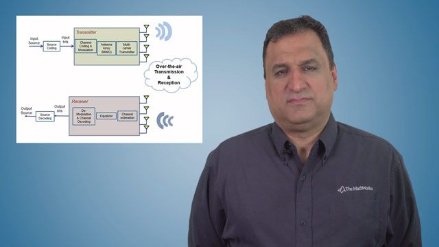
    You can transform the connected radio into a baseband receiver, baseband transmitter, and baseband transceiver, operating at full device rates. The use cases and applications of baseband receiver is to capture signals, such as 5G, LTE, satellite, and custom signals from the air. The baseband transmitter can be used to transmit custom or standard-based waveforms, transmit noise, or interfering waveforms. The baseband transceiver can be used to analyze channel effects, such as signal attenuation, and multi-path, assess the performance of radio hardware and analog frontends. The transceiver also enables loopback workflows.

    This figure is high level representation of the baseband receiver. You can create a baseband receiver by specifying the name of the video configuration. The baseband receiver can be used to capture baseband samples from the air. The captured data is put forward in the onboard RAM of the supported USRP hardware to ensure contiguous and high-speed data capture. Baseband receiver supports full range of sample rates supported by USRP hardware.

    The baseband receiver provides a capture function to capture baseband samples from the air. This function also monitors if samples are dropped during the capture. The code shows how you can use baseband receiver to capture three milliseconds of data at the set sample rate. This diagram shows the baseband transmitter provided by Wireless Test Bench.

    You can easily convert a supported USRP radio into a baseband transmitter from MATLAB, and configure the specified radio to transmit baseband samples to the air. The transmitter uses onboard RAM to achieve high-speed transmission. You can configure continuous or single-shot transmission from MATLAB. The baseband transmitter provides transmit and stop transmit functions. The code here shows how you can transmit at a specified sample rate for 5 seconds and then stop the transmission.

    This figure shows the high-level architecture of the baseband transceiver. You can easily create an object or baseband transceiver in MATLAB to simultaneously transmit and capture AUV forms over the air. The baseband transceiver also uses onboard RAM to operate at maximum sample rates that are up to 250 megasamples per second. You can configure continuous or single-shot transmission.

    The baseband transceiver provides transmit, capture, and stop transmission functions. The code shows how you can use a baseband transceiver for for loop back work force. You can transmit a random signal and capture it into MATLAB workspace.

    Let me show you some examples to demonstrate high-speed data offered by Wireless Test Bench. This example shows the baseband receivers capability to capture a signal from the air in specified frequency band. Firstly, you provide the name of the radio configuration that user can set, during the USRP radio set up. You can refer to the product page or documentation and look for simple radio setup to know more about configuring the radio with MATLAB.

    Then, we specify the frequency band that we wish to capture. In this case, the selected band is allocated for FM radio. Next, we configured the baseband receiver and set the RF properties, such as sample rate, sensor frequency, radio gain, and antennas. Then, we invoke the capture method to capture one second of data. Finally, we plot the spectrum of the captured data using the spectrum analyzer.

    One can see that whole FM frequency band is visible. The vertical red lines in the spectrogram are FM radio stations. You can demodulate and listen to any one of these FM stations.

    In this example, we will capture using multiple antennas from a specified frequency band. Using multiple antennas, you can capture a wider frequency band, by setting different center frequencies for different channels. Firstly, we set the name of the radio connected to MATLAB. Then, we specify the frequency band that is from 470 megahertz to 624 megahertz that is used for TV broadcasting, which is 224 megahertz wide spectrum.

    Next, we set the RF properties, such as antenna array, center frequency for each channel, sample rate, and radio gain. The sample rate and central frequency are set, as each channel will contain one half of the spectrum of interest. Then, we capture the signal 100 milliseconds using capture function.

    The capture function returns the data matrix where the two columns correspond to the two channels. Next, we sample the captured data and shift the spectrum to plot the complete frequency band together, as each channel will contain one half of the spectrum of interest. Finally, we plot the spectrum using the spectrum analyzer, and one can see the complete 224 megahertz wide spectrum used for TV broadcasting.

    In this example, you will see how the baseband transceiver can be used in bluepack to transmit a signal and receive it on the same radio. Firstly, we choose the radio that is connected to MATLAB. Next, we load a known waveform, from a file, that will be transmitted over the air. In this example, I have chosen a sine wave. Then, we create baseband transceiver object.

    Next, we set our properties, such as sample rate, that is corresponding to the sampling frequency of the waveform to be transmitted. TransmitCenterFrequency-- that specifies varying frequency spectrum. Our signal will be transmitted. CaptureCenterFrequency-- with same as TransmitCenterFrequency and radio gains. Then, we transmit the waveform continuously.

    Next, we invoke the capture function, to capture for the specified duration of data. The capture function returns a column vector that should contain our signal. Then, we stop the transmission.

    Finally, we use spectrum analyzer to plot frequency spectrum of the received data. And one can see the peak that corresponds to my signal-- that was a shining shoot. You can refer to the product page to know more about high-speed data I/O feature, and other capabilities offered by Wireless Test Bench. you can also see the documentation for getting started guide and tutorials.