Modeling a Three-Phase Inverter | How to Design Motor Controllers Using Simscape Electrical, Part 2
From the series: How to Design Motor Controllers Using Simscape Electrical
Melda Ulusoy, MathWorks
This video shows you how you can model a three-phase inverter using Simscape Electrical™.
Download the model used in this video.
Published: 6 Sep 2019
In this video, we’ll show you how you can model a three-phase inverter for converting a DC power to three-phase currents to control a BLDC motor.
This is the model we built in the previous video. Here we had a scenario where we turned the motor shaft and measured the back-EMF at one of the open phases. This time, instead of operating the motor as a generator, we’ll drive the motor by energizing one of the coil pairs using an inverter model.
Throughout this video, we’ll be referring to our Tech Talk video where we discuss the control algorithm including the three-phase inverter and commutation logic. So you may want to check it out before watching this video to understand how these components work. In this video, we’ll focus on this part of the algorithm and in the next ones, we’ll work on the rest of the model.
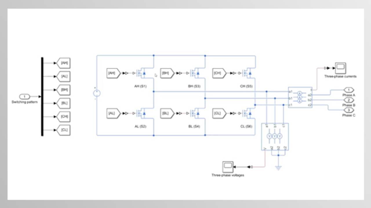
We removed some of the blocks from the previous model since we don’t need them for modeling the inverter. After adding the load inertia and entering its value, we can start working on modeling the three-phase inverter. This picture from our Tech Talk video will help us with modeling the inverter. A three-phase inverter is basically a circuit that converts DC to AC current using three pairs of inverter switches, each corresponding to a phase. Based on how you want to model the three-phase inverter, you can choose from different options that are available under the semiconductors and converters section in Simscape Electrical.
In this example, we’ll use MOSFETs. You can use the data sheet of your power inverter to specify the parameters of this block. Now, we’ll try to build the same circuit as in this picture by inserting the necessary blocks and connecting them together. Let’s start with the first pair of switches that control the phase A currents. We simply duplicate the switch and name the upper one AH as it’s the high side switch, and similarly, label the lower one as AL for the low side switch. S1 and S2 show the switch numbers. The DC voltage input to the inverter can be modeled using the voltage source block.
Now we can connect this circuit to the phase A as seen on the picture. We can complete the rest of the circuit by copying and pasting this pair of switches. The input to a MOSFET is either a high or a low signal to turn it on and off, respectively. As we discussed in the Tech Talk video, for running the motor properly, we need to drive the correct phase pair at the right time. In the control algorithm, this decision is made by sensing the angular position, and based on that, computing a switching pattern to the three-phase inverter. We’ll be modeling those parts in the next video.
In this video, we’ll assume a static switching pattern where we only energize phases A and C, and we then will observe rotor motion. We can model this static switching pattern using a vector of six constant values for driving the six switches either on or off. To distribute this vector of values to corresponding low and high side switches, we can use a demux block along with “goto” and “from” blocks. This way, we get a clean look by connecting two signals together without showing any wires. Here, we need to convert the Simulink signal, which is either 1 or 0, to a Simscape signal before connecting it to our circuit. The rest of the ports can be connected using “goto” and “from” blcoks.
Now, to measure the currents and voltages that will be supplied to each of the phases, we can use the phase voltage sensor and current sensor blocks. By right clicking the block and choosing this option, we can expand this port to display the three phases. Let’s do the same for this sensor as well. If you were in a lab and wanted to measure the current with an ammeter, you would connect its terminals in series with the circuit. Similarly, in simulation you connect the current sensor in series. The port I outputs the measured three-phase currents which we connect to a scope for visualization after converting them to Simulink signals. And for sensing the voltage, we connect the sensor in parallel between the electrical nodes of the motor. Similarly, we connect the output port to a scope.
Let’s select these blocks and create a subsystem, which we’ll rename as the three-phase inverter. In this video we showed how you can model your own three-phase inverter from scratch, but note that you can also find a built-in block for the three-phase inverter in the Simscape Library. This block lets you choose from different switching devices such as an ideal switch, MOSFET or IGBT for modeling your inverter.
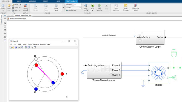
To explore the rotor motion, we need another sensor to measure the speed. For that, we use the ideal rotational motion sensor block, which outputs the motor speed and position through the ports W and A, respectively. We set the initial angular position to 0 degrees in the motion sensor block. Also note that these conversion blocks let you define units, so you don’t need an additional block to convert between degrees and radians. Next, we name the “switching pattern” and “angular position” signals. We then log them by right clicking on each of the signals and choosing this option. We have a MATLAB script which automatically runs this Simulink model and then uses the logged signals to create an animation of the rotor position. To see this animation let’s go to the command line and run the script by typing its name and hitting “enter”. Here, we see the energized phases A and C and the resulting rotor position. If you watched our first Tech Talk video, you may remember that we discussed how energizing different coil pairs leads to different rotor alignments. In this video, we showed you how you can model this in simulation and experiment with your model. In the next video, we’ll work on the rest of the control algorithm and simulate different characteristics of the motor.
Download Code and Files
Related Products
Learn More


Seleccione un país/idioma
Seleccione un país/idioma para obtener contenido traducido, si está disponible, y ver eventos y ofertas de productos y servicios locales. Según su ubicación geográfica, recomendamos que seleccione: United States.
También puede seleccionar uno de estos países/idiomas:
América
- América Latina (Español)
- Canada (English)
- United States (English)
Europa
- Belgium (English)
- Denmark (English)
- Deutschland (Deutsch)
- España (Español)
- Finland (English)
- France (Français)
- Ireland (English)
- Italia (Italiano)
- Luxembourg (English)
- Netherlands (English)
- Norway (English)
- Österreich (Deutsch)
- Portugal (English)
- Sweden (English)
- Switzerland
- United Kingdom (English)