Implementing Motor and Power Electronics Control on an FPGA-Based SoC - MATLAB & Simulink
Video Player is loading.
Current Time 0:00
Duration 33:06
Loaded: 0.50%
Stream Type LIVE
Remaining Time 33:06
 
1x
  • descriptions off, selected
  • en (Main), selected
    Video length is 33:07

    Implementing Motor and Power Electronics Control on an FPGA-Based SoC

    Overview

    Wide-band gap devices such as SiC and GaN power electronics let converters and drives operate at higher switching frequencies than Si devices. Faster switching means smaller passive components and less power consumption.  An FPGA-based system-on-a-chip (SoC) can execute algorithms at the speeds needed to support motor and power control applications using these devices.

    Simulink, Simscape Electrical, and HDL Coder let you design your control algorithms and deploy them as HDL code to FPGA SoCs.  With these tools, you can use simulation to test your algorithm against a model of a motor and inverter or power converter, letting you perform design tradeoffs and analyze system performance.  As well as generating HDL code, HDL Coder provides a workflow advisor to help you evaluate your HDL architecture and implementation, highlight critical paths, and generate hardware resource utilization estimates.  Using SoC Blockset lets you simulate memory and internal and external connectivity, as well as scheduling and OS effects, using generated test traffic or real I/O data.

    Highlights

    In this webinar, MathWorks engineers will show:

    • Automatically deploying code to both processor and FPGA in an SoC
    • Partition a motor control algorithm between processor and FPGA in the same model
    • Generate c-code and hdl from the Simulink Model

    About the Presenters

    Shang-Chuan Lee is a Senior Application Engineer specializing in Electrical system and Industrial Automation industries and has been with the MathWorks since 2019. Her focus at the MathWorks is on building models of electric motor and power conversion systems and then leveraging them for control design, hardware-in-the-loop testing and embedded code generation. Shang-Chuan holds a Ph.D from the University of Wisconsin-Madison(WEMPEC) specializing in motor controls, power electronics, and real-time simulation.

    Joel Van Sickel is an Application Engineer focused on power electronics and FPGA based workflows for both HIL and controls.  He was a hardware design engineer prior to coming to MathWorks in 2016.  He received his Ph.D. focused on power systems and controls from the Pennsylvania State University in 2010.

    Recorded: 22 Feb 2022

    Hello, everyone and thank you for joining us for How to Implement Motor and Power Electronics Control With an FPGA-based SoC. My name is Joel Van Sickel. I'm an application engineer at MathWorks. I work in the Novi area. I do a lot with electrification.

    My background was a hardware design engineer. And some of that was designing matrix and cyclic converters which were controlled with SoCs. So that's why I'm here.

    Hi, everyone. My name is Shang-Chuan Lee. I'm also part of application engineering team at MathWork. Before joining MathWork, I was a motor control engineer focused on designing control algorithms to make sure motor drive system meets its performance requirements and its robustness of the overall system. So today I'm really happy to join Joel and share our perspective how model-based design can help with motor and powertrain controls, especially FPGA-based SoC.

    Yeah, so before we get started with the agenda and everything, we're going to show you what our end goal is with a workflow like this. And we have a video recorded by one of our colleagues who has the hardware accessible. Before I start it, just take a look up here.

    This is just a 30 watt PMSM. And it's hooked up to, this is the SoC. This is a Xilinx product. And this is a development board plus a little add-on kit that has an inverter so we can use it for a demo. This was sized so that we can travel with it.

    Unfortunately, we haven't been able to do that much. But we can still at least show you a recording of what's going on. And so he's compiled the entire program within Simulink. He's running it from Simulink that's connecting to this motor. You can see there's a piece of tape on the shaft so that you can at least see that it's spinning.

    I mean, we are getting all of the feedback data into that so we can see it. This particular algorithm is doing velocity control. As you can see, we're just taking it through different rotor velocities, which makes sense because there's no load in this particular case.

    We're not hooking up to a Dyno or anything. This is using field-orienting control. And one of the nice things about this approach is that he was able to do this without ever leaving the MathWorks environment.

    So Simulink takes care of both the C code generation for the processor and the FPGA code generation for the fabric slash FPGA. It calls whatever third party tools you're using in the background, builds, synthesize, implements all of that, downloads it on to the SoC, lets you control it without having to actually open up the other tools.

    And so it's a very streamlined workflow and it handles a lot of the more nuanced pieces like the communication interfaces for you so that you can focus on implementing your algorithms. So now that we've given you an idea of what can be done and what the tools do, let's get into the meat of the presentation.

    So for our agenda, what are we going to talk about today? One, we need to talk about, why would you use an SoC for these type of control algorithms? There's a lot of benefits. But there are some disadvantages.

    So we want to have an honest conversation about what are they really good for and where might you not want to use them. Then, another issue is that not a lot of engineers actually have much experience with SoCs. So we need to explore, what are they? Why do they have a more complicated design process in exchange for the benefits they bring?

    And finally, you know, we're MathWorks, we're application engineers, we're going to make a pitch to you. So we are going to talk about why do the MathWorks tools help make this type of design easier?

    And so specifically, we'll talk about modeling, how do you partition the algorithm, and generating code. So the first two bullet points will be mostly PowerPoint presentation. And then Shang-Chuan is actually going to explore the Simulink model that created the demo we just showed you the video of.

    So to the first question, why use an SoC, particularly an FPGA-based one, for control application. As I mentioned, I have a power electronics background, a hardware design. Wide bandgap materials have always been very exciting to me for what they can do as far as switching frequency perspective and their thermal capabilities. So really, letting you get higher power densities because of that.

    And it opens up things with thermal where you can run things hotter. But to take advantage of those, you have to run at much faster loop rates. You can see here, this is an image of a battery charging an EV vehicle. What you'll see is, obviously, for onboard chargers, smaller is better for those. And for the chargers that are in place, they have a lot of issues as far as they have stringent power quality requirements because they are connecting upstream to the grid.

    Obviously, they care about efficiency. And their voltage and current levels make them really ideal for certain topologies like resonant converters. And there's a lot of opportunities in this space for using these wide bandgap materials and having these faster loop rates. But Shang-Chuan might mention that I'm a little obsessed with loop rates. But there's more to it than that.

    Yeah, Joel, as a motor control engineer, I think FPGA in motor control space can be helpful. It's because we see a need for designing complex control algorithms. So I can take my previous working experience at industrial drive application as example.

    So I believe most of you may be familiar with FOC it's like a standardized torque control. But now we see simple control is widely adopted in motor drive system due to its benefit of reducing calls for sensors. But one caveat is that this type of advanced control algorithm means higher computation effort. So it will potentially sacrifice our controls performance. So in my opinion, I think FPGA could be a solution to address this limitation by partitioning control algorithms.

    That's a fair point. And something else we learned, this is from one of our colleagues who does a lot in the utilities side. He's not here with us but he works in Shang-Chuan office. He does a lot with MMCs. And some of his control algorithms aren't that complex. And they're running a much slower loop rates.

    However, he will literally need hundreds of I/O for his control application because of the modular design aspect. So for him, the most exciting part of SoCs and FPGAs is just the sheer number of I/O that they can facilitate in your design. To illustrate this a bit more explicitly, we do have a public user story about one of our customers who is using SoC-based control through our tools. That's pretty relevant to the workflow we're demonstrating today. So we want to walk through that to give you an idea how our real customer's impacted by their need to use SoC-based controls.

    So Punch Powertrain is doing e-drives for consumer vehicles. And they were looking at types of motors. They chose they're going to do a direct torque control. And they're going to do it for a switched reluctance motor. And particularly, just to make it so the sound was bearable for a typical user, they're going to have a lot of requirements on their control algorithm that made it much more complicated than, say, standard FOC-based controller for a PMSM.

    And as they're investigating this, not only did they need to use these more advanced control algorithms, they found that even a one microsecond delay in their loop caused an error of eight amps. So they had that issue where they need to run this much faster than they'd typically be able to run on a processor-based controller. And they also didn't have FPGA knowledge within their company.

    And so that makes it very challenging to pursue taking advantage of these types of technologies if you don't have anyone who understands them. So at the end of the day, they needed to go from 70 kilowatts to 130 kilowatts. And they needed this complex control algorithm essentially running faster than a microsecond.

    And this is something that, especially for them, was going to be really challenging to do timely because of the lack of expertise. But using our tools, they were actually able to get something working, do live demonstrations within 18 months. Now, there's an entire 24-minute video where they walk through this and show demonstrations. That is on our web page.

    But this really highlights how I often am worrying about loop rates and Shang-Chuan is often investigating more interesting control algorithms. The reality is most customers want to do both. They want their loop rates to be faster. And they want to use more advanced control algorithms. And Punch Powertrain is a perfect example of that reality.

    So we've talked about a lot of the benefits of using an SoC, such as you can get these faster loop rates, you can do more complex algorithms, you have more I/O available to you. What are the challenges? Well, the biggest challenge of using an SoC just comes from how it's set up. The very thing that gives it its benefits also are what makes it challenging.

    So an SoC is a single chip. But on that chip, you'll have a processor core. And this is where a lot of people have a lot of experience with processors for embedded systems.

    But then you'll also have programmable logic. You can call this the fabric. This is the FPGA. This is where you get a lot of additional power. But it also adds complexity to your design because part of your design needs to be on the processor and part of your design needs to be on the programmable logic.

    And then all of that is stitched together on a single chip. So this is really ideal because you could always put a processor and FPGA separately. But then you're going to have to do the layout and connect them with high-speed lines. Having all of that integrated on a chip gives you these AXI buses with really high throughput and you don't have to worry about any of the layout issues.

    But you do have to worry about, you're in control of synchronizing them. You're in control of passing the information between them. You have to decide what's on the FPGA side, what's on the processor side. And especially because this is a newer type of workflow, there's not a lot of established best practices.

    There aren't a lot of engineers with a ton of experience in it. And so that's where the challenge comes from is that it's just a more complex chip to program than if it were just an FPGA or just a processor. Diving a little deeper so that you can understand a little bit of the nuances behind the two cores that are on it.

    For processor, this is typically programmed with something like C code. This is one of the more common programming skills you'll find in engineers. And that eventually gets compiled down to zeros and ones. And you stick that on the processor.

    So the nice thing about this workflow, it's easier to modify. The compile and build process might not be the fastest. But it is actually pretty fast. It's easy to design algorithms. Most people think well in this sort of sequential task approach. And because C is a sequential programming language in most cases, it's very convenient for debugging.

    So it's much easier to debug algorithms you're deploying to a processor than to the fabric slash FPGA. On the FPGA side, things may look a little similar at first. It's like, OK, this looks like a programming language.

    So you have VHDL and Verilog for FPGAs. But they're not sequential programming languages like C is. And there are much less intuitive for most people because everything can be happening simultaneously. It can be happening asynchronously or synchronously, depending on how you design it. It's not as intuitive a programming language.

    Also, when it gets compiled, it then has to go through synthesis and implementation. So instead of being translated into zeros and ones, it's actually translated into this map of logic gates. And so the FPGA fabric is just hundreds to thousands of these logic gates that you can stitch together in arbitrary combinations to get the circuit you want. And this process takes much longer than a compile-and-build process in C code.

    Oh, hold down, Joel. I think I'm quite familiar with generating the code for C or C++. But really, I never see you showing me how the synthesis process for FPGA. So I'm curious, how long does it really take for synthesis with respect to compile time.

    That's a fair question. So some background information, Shang-Chuan has seen me present similar workflows for hardware-in-the-loop. And I usually just skip the step where we actually do synthesis. And that is because the synthesis for those designs on my laptop typically takes two two, two and a half hours.

    If I put it on my workstation, we're looking at closer to an hour, hour and a half. Now granted, the Hill models are more complex typically than an SoC-based control algorithm. But for this type of control algorithm, you're still typically looking at something that's going to be over 30 minutes and could get you up into an hour and a half, especially depending on your processor speed. And that really does change the workflow.

    Even though you can design both algorithms in Simulink, have them in the same model, the fact that if you change it on the FPGA side, you have to wait two hours before you can test your changes, whereas on the processor side, you can be up and running again and maybe 10 minutes. That does actually help determine, where do you want to put certain algorithms?

    And so that is something you need to be aware of when you're doing this type of programming. If you have an FPGA background, that doesn't come as a surprise. But for people who focus more on the processor side, that really is kind of culture shock, like, oh my goodness, I made a change. Now I have to wait two hours before I have anything to test. So that's something to be taken into account.

    And so that is where the FPGA side is what is a big challenge for most people. For Punch Powertrain, they didn't have anybody with this background. So you do get these benefits. You get this large computational throughput because I can literally do hundreds of logic operations simultaneously.

    Or I can do a few really complex calculations simultaneously. I don't have to worry about multithreading or anything like that. I can just do it all in parallel. There's the high number of I/O, which can be very useful, depending on your situation.

    And this all adds up to letting you get faster loop rates than you can do with a typical processor. However, as I mentioned, it's a more challenging design. It's less intuitive. And when you make a change, it's going to take longer before you can actually examine it.

    Now, there are emulation tools that help you address some of those issues so that you can test things without synthesis. But that's getting kind of advanced on the FPGA V&V side. So the SoC takes both of those, the processor and FPGA, marries them together. And so you get the best of both worlds.

    But you get the worst of both worlds, plus the complexity of needing to stitch them together. And one of the benefits of using our tools is that, in most cases, we'll handle the communication interface between the processor and FPGA for you. You always have the option to hand customize it yourself, but in most cases, we can set up the AXI stream and do all of that for you behind the scenes so that you're not worrying about communication algorithms.

    You're just focusing on how to you solve your problem. What do you want to be on the processor? What do you want to be on FPGA?

    So now, we've finally gotten through a lot of the big picture stuff in an introduction. So I'm going to do a little bit more high-level stuff. And then we can finally dig into the model. So if you are using our tools, how would you approach an SoC-based design. Now, there are a lot of things you can do with fixed-point designer to optimize these algorithms. And there's a lot you can do with controlling your loop rates.

    There's a lot of stuff you can do. But the best thing to start with is to just not worry about that. Just build a normal Simulink model. Use floating-point algorithms. You can even use continuous-time algorithms if you want. And build a working closed-loop controls with your plant model.

    And the reason I say that is because once you have a working control algorithm, you can use Simulink to do a trade study on what the best thing to do is. So you can investigate, I can partition my algorithm in different ways. I can run it at different loop rates. I can run it with different data types.

    You can do all of that within Simulink and actually come up with quantitative reasons for why you're going to partition the algorithm the way you are. You're going to see, what's the fastest loop rate I need. So for instance, Punch Powertrain was able to identify that that one microsecond delay was eight amps of error. And they can do that because Simulink can model both the continuous time domain and the discrete time domain what would happen, even if you haven't actually come up with an algorithm that does that in the real world.

    And so Simulink lets you explore that design space before doing any actual optimization for your hardware. Now, once you have gotten that far, you are going to want to do the hardware optimization. It is going to be worth it to take your simulation model, even if it generates code and works, it's worth it to take it through the fixed-point tool and optimize it. And so this is that one extra piece of complexity that a lot of processor-based workflows might not have to deal with.

    There are a lot of floating-point processors out there, and the most people who work with FPGAs are pretty used to having to do the fixed-point design anyway. And so it's worth stopping here because, again, most of the people in this audience have a stronger processor-based background than FPGA-based background.

    So we're going to take a little aside to discuss why fixed-point design is worth the time and effort to put into it. The easy way to do that is to show you the difference between the resource usage of a floating-point algorithm and a fixed-point algorithm. This is the SoC-based controller that we did the demo with. This is the resources it uses if we generate HDL for it for floating point.

    So we can generate HDL that works for it floating point. But just look at the fact that there's 3,600 registers and about 40,000 total one-bit registers, as an example. If we take it through the fixed-point tool, which does take some work, we now have 66 registers as opposed to 3,600 and 1,000 one-bit registers as opposed to 40,000.

    So we're talking, for a lot of these resources, we're looking at orders of magnitude difference and usage. And that has energy-usage benefits. It might mean you can actually run at a faster loop rate because the electrons will literally be able to propagate through the circuits faster. But also, it lets you buy cheaper hardware.

    So this is just me pulling two versions of an SoC off of Digi-Key. So the higher end one that has more resources so that you could put more on it, it's going to cost around $300 per unit. And if you get one with slightly less resources, it's going to be $60. So in this case, that's a factor of five difference in cost for your controller if you optimize the algorithm enough to fit on the smaller controller.

    So whether this matters is really dependent on your area because I did a lot of defense contracting. Some of those, you were going to make 10 units over the lifetime of the design. We didn't optimize to get cheaper controllers. But now I support automotive where it's usually worth design effort, even if you can only save a few cents.

    So whether you need this price savings is really dependent on your market and how many units you're going to be manufacturing. But I would say 99 times out of 100, our customers go through with the fixed-point design when they're targeting their production hardware. So when it comes time to do that, we do have this tool that has a systematic process through going through that. It does speed it up because it's not easy to know all the different data types you should do.

    Again, this could be two webinars in itself. It's just important to know it's out there and available. And we don't want to hide pieces of the workflow that you need to do to take advantage of SoCs. They bring a lot of power. But you are going to have to put more effort in on the design stage.

    And our tools are really set there to minimize and give you a systematic way to go through that effort. But so enough about talking at the high level. I am now going to hand things over to Shang-Chuan and she's going to show what this algorithm implementation looks like when you're doing it in Simulink.

    So, thank you, Joel. So, yeah, here is the simulation model for field-orientation control test bench. And this is the model that Joel was showing you in the very beginning how we can being a real motor typekit by deploying the code to xylene think SoC port. And here, you can see just a very high level, we have a system input of a command of velocity, control algorithm and also the physical model for modeling the plan model, motor and power train makes all the sensors.

    That is modeling and continuous time domain. So as you can see, it's a system-level simulation for a closed-loop field orientation control. So just let me quickly press this Run button and you will see the simulation result we are interested to looking at.

    So as you can see, doing the simulation, here we can validate our speed response and current response and also controller mode scheduler mode. As you can see, the speed command is pretty much aligned with speed feedback. And also, on the third also scope here, we also implement a mode scheduler. So that's why you can see a change of controller mode at different time stamp such as standby mode, encoder position, calibration, and then closed-loop control.

    So as Joel mentioned earlier, this is a no-load torque control. Essentially, it is validate that the current face current is zero at this point. So with model-based design, we can validate a closed-loop control in a desktop simulation.

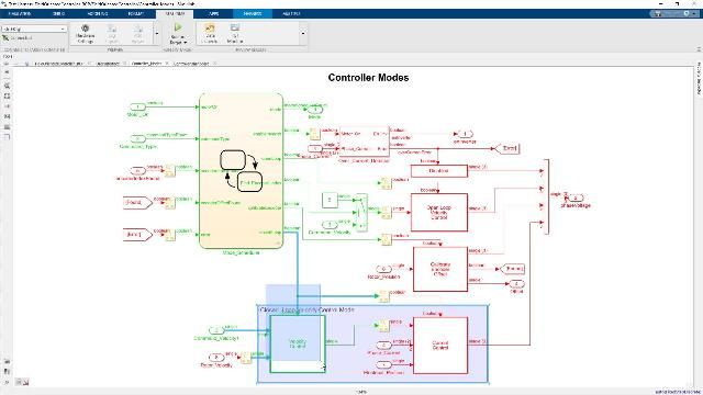
    And now let's dive into control algorithm side. So this is where we need to make a decision how can we partition control algorithm, right? So which portion of control algorithm we want to deploy into ARM processor versus FPGA fabric? So in this case, we have an inner loop of field orientation control. And also, we also got the outer loop of speed control loop with controller-mode scheduler.

    So for FOC control, it's usually simple at a relative faster loop rate because we like to achieve high performance torque control. Just like Punch Power, they were implementing PTC direct torque control to achieve high performance motor drive system. So that being said, with model-based design, we can easily petition advanced motor control algorithms into a SoC design.

    Right, so I guess the next question you might wonder, how do we generate the code and deploy into an embedded processor, right? So in this case, we can start with the speed-control loop. This is where we want to generate the code from the smaller sample rate.

    And we can open up this model reference for speed-control loop we got the mode scheduler implement by Stateflow chart. And the reason is because we can decide which control mode we want to select based on which mode we want to do, either open-loop control or close-loop control or sensor position calibration mode.

    So to generate the code, you will go to Apps, and under Embed Decoder and it's very straightforward. You just press the Generate Code. And withing a few seconds, we can quickly generate the code. It's a code gen report. So essentially, it's a C file and F file here that already generate out of model.

    And it's a NCC code and it's portable. And you can take it. You can integrate it with any target processor. So what about fuel orientation control because we are intended to generate HDL code out of FOC, right?

    So in this case, you will see they are some of the building blocks around field-orientation control like an input port here and output signal here. And the reason is because we want to make sure we can meet both functional and timing requirements of the HDL code while interfacing with the embedded processor. And we want to make sure they will communicate really well with the AC buses.

    So to generate HDL code, we can also follow the same path. And this time we can go to HDL Workflow Advisor. So essentially, HDL Workflow Advisor facilitate the HDL and Verilog test bench generation from your Simulink model.

    So we're seeing a Workflow Advisor. You can set up a third party target like I show you here. You can choose the IP code generation and you can choose which platform you are interested to target with. And you can also set up the synthesis tools.

    So just following through a Workflow Advisor step-by-step, we can provide this guideline and it will help you check with model compatibility, model settings. So it can help you to easily generate HDL code through this whole process.

    So as Joel mentioned earlier, it's going to take a long time with synthesis process. So I will just show you a vhd source file that we are ready generate from this project. So as you can see here, this is the FOC that vhd file that we already generate.

    Now here is the code. You can just take it for integrate into your SoC design. So now I will hand it over to Joel and he will wrap up the webinar.

    So this makes me happy because now Shang-Chuan is the one who skipped showing the actual synthesis of the HDL code because I've always been the one skipping it. And now she can't harass me for the fact that I skip it because she now is also aware of how long it takes.

    But as far as the summary goes, when you start, use Simulink to model your algorithm in your plant just like you would any other approach. Once you have a good idea of the controller elements you want to use in their ideal state, that's when you can go in and start studying the nuances of splitting the algorithm.

    So like those unit delays Shang-Chuan showed you on the HDL side, if for some reason you had a slower communication interface, you can increase those delays to simulate the effect of a longer time for the communication algorithm to go through. So you can simulate an ideal scenario where all the information goes instantly. But you can also simulate it with the delays caused by execution, communication, sensor delays. You can incorporate all of that into your model. So you can really study the nuances of how splitting it's going to affect your performance in the real world.

    And finally, once you've done that, that's where you generate the optimized code for your target platform. That's where you bring in the fixed-point control. One thing we haven't really talked about in this meeting but is probably the most important takeaway is that you can contact MathWorks for more support.

    So for instance, I provide international support. Shang-Chuan provides a lot of support in the US. We've both worked multiple times together on SoC projects with customers. We have a lot of counterparts who also have the correct background to work on SOC designs.

    And hopefully, as you've picked up from this webinar, there are a lot of nuances to it to evaluate as far as the benefits and challenges you might run into for a particular application. And you don't have to guess at it. We can talk you through the process. We can tell you what you would need to do as far as setting up models to correctly investigate those nuances. This isn't something you have to walk through alone.

    And so Shang-Chuan and I will be providing our emails on the next slide. We're going to do a Q&A. So please feel free to type in your questions. You will also be getting a copy of the slides for this if you registered. But that doesn't happen right away. It's probably a couple of week if not a month delay.

    So I'm going to take us to the Q&A slide. Please feel free to email us. Most people don't. Most people don't reach out. So we have never been overwhelmed by a stream of emails from putting these up publicly.

    So don't feel bad in reaching out. So we'll start looking at the Q&A now and answering your questions.

    View more related videos