Deploying a Control Algorithm | Design and Test a Grid-Tied Solar Inverter Controller, Part 4
From the series: Design and Test a Grid-Tied Solar Inverter Controller
Learn how to deploy and test a grid-tied inverter control algorithm. Specific tasks that are covered include,
- Automatic Code Generation for C and HDL code
- Deployment of the physical plant to CPUs and FPGAs for hardware-in-the-loop testing
- Deployment of the control algorithm to a microcontroller
- Verification and validation
- Test normal and abnormal operating conditions
Published: 6 Jul 2022
So once we're happy with all of our controls response-- we've tuned it, we've tested maximum PowerPoint tracking, we've tested against grid code compliance-- we can take all of that work we've already done in Simulink and directly convert it into embedded software that can target a device such as a TIC 2000.
With our tools, we have code generation technology that can convert blocks to just raw C code. But we also have hardware support packages that can target specific devices and add things like driver blocks to target things like their PWM generators.
And so, essentially, you take that same model that we've built, convert it into C. That can then be compiled using a tool like Code Composer Studio and then deployed directly to the processor for use.
So this is how we could take all of this controls that we've built and deploy it. Carlos, could you walk us through the process of how we could start to do hardware-in-the-loop testing using that plant model that we've built?
There's a similar process for the code generation with the Speedgoat Real-Time Target Machine. With Speedgoat, we used Simulink Real-Time and HDL coder to automatically generate code both to the multi-core CPUs and to the FPGAs.
There's also a wide range of I/O connectivity that we can use, communication protocols, and functionality. This functionality could include PWM, PWM capture, quality encoders, et cetera. We have driver blocks, Speedgoat driver blocks, that we use to connect to the Simscape and Simulink components.
In this case, we see for example, a PWM capture signal being directly linked to the two-level inverter. In this way, we'll be using the switching function and the switching function with signals coming directly from the FPGA. And we also have an analog block.
Then we automatically generate C and HDL code. And we can deploy using the Simulink Real-Time to speed code with computers. We can have a single machine or a combination of them in rack, combining several multi-core machines together with low latency links.
Now, let's start the hardware-in-the-loop testing. Briefly, let's quickly let's just recap on its advantages. We can resue models at different levels of fidelity. We can do automatic code generation.
And then we'll be using-- we can use Simulink and Speedgoat hardware together with validation and verification tools, such as Simulink test. And we can use HIL testing with switching dynamics up to 5 kilohertz with the CPU. And we can go much higher when we go to the FPGA.
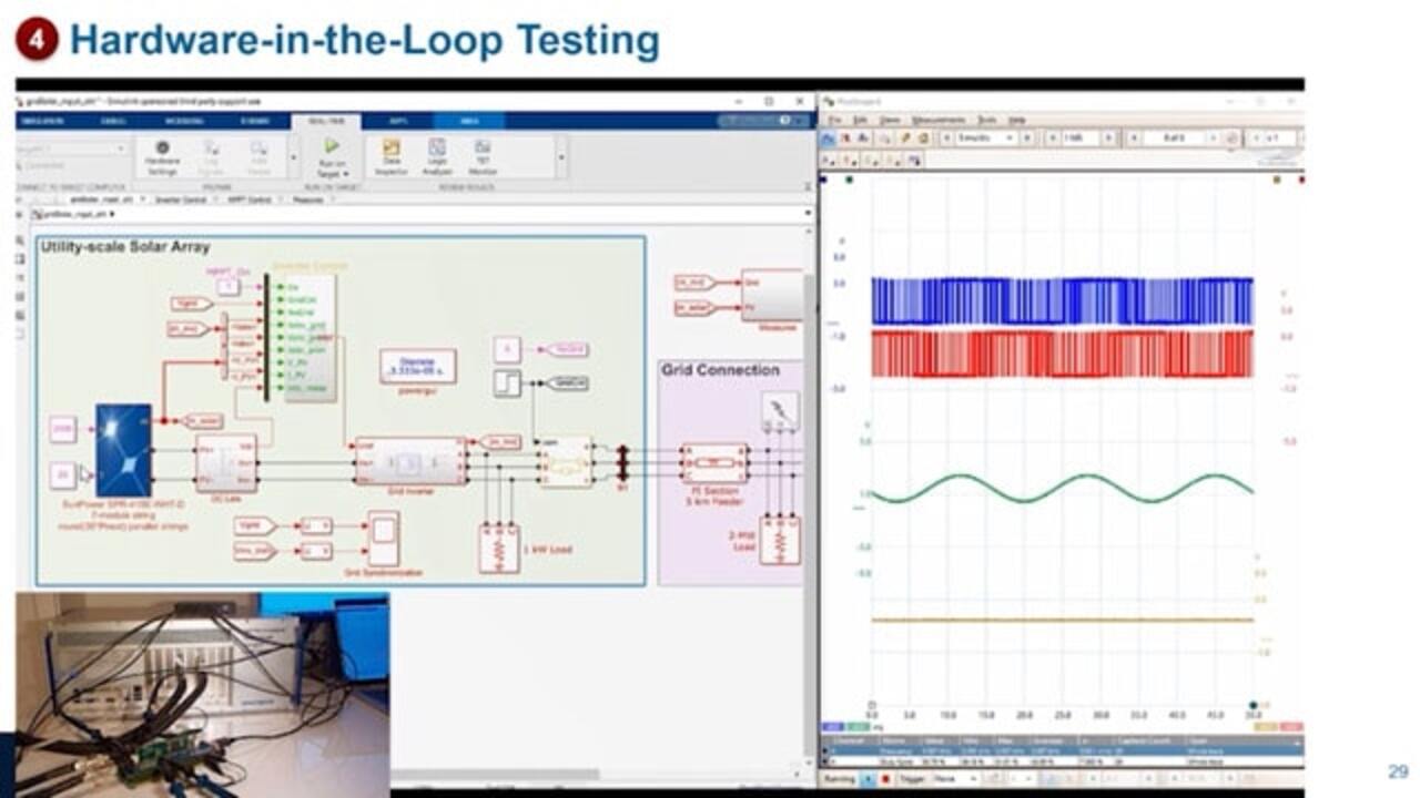
In this case, we'll be using 5 kilohertz. So we have our Simulink model ready. Here we have hardware-in-the-loop, the model that we'll be using for hardware-in-the-loop testing. We have the scope from the oscilloscope with two PWM faces.
The green line is going to be the voltage measured from the inverter. And the orange line is going to be the current. These are all measurements taken from the PicoScope with the interfaces between the microcontroller and the performance target machine.
So we initially had our desktop simulation, but that's not the controller in our desktop simulation. But as it is now in a microcontroller, we replace it with Speedgoat driver blocks. Here we have the analog, SPI communication, and PWM capture.
The different blocks, the different colors represent the different sample times. The green represents the controller sample time. And the red represents the plan simulation sample time. The plan simulation sample time is much faster than the controller sample time in order to capture the switching dynamics.
We are running at 33 kilohertz. Now we deploy. And we're generating code to the Speedgoat target machine, which is already connected to the Texas Instruments microcontroller via these two cables to the performance target machine. We we're measuring all the signals in between-- four signals in between using a PicoScope.
So let's start the simulation. Initially, we're disconnected from the grid. A second end will be connecting. We can see the two phases of PWM and the voltage of the inverter.
After 10 seconds, we see that the current increases as we connect it to the grid. And we're starting to generate to provide energy from the solar panels. As irradiance reduces, the current also reduces, and it goes back up as the irradiance increases again.
If we zoom in with the PicoScope, we can see the PWM switching. And in the background we have the 60 Hertz signal.
If we go inside the inverter model and we measure the current, we can see the switching dynamics of the current. These oscillations have a 200 millisecond period that is corresponding to the 5 kilohertz switching of the PWM.
To summarize, we have shown how to develop a controller for a grid tie solar inverter. We used Simulink and Speedgoat hardware to design this controller. And we were able to reuse the models between desktop simulation and hardware-in-the-loop testing.
These models, we were able to generate C and HDL code automatically from Simulink and Simscape Electrical. And finally, as a third take away, that you can use hardware-in-the-loop testing to test not only normal operating conditions, but also fault conditions such as fault Fault-Ride Through.
Related Products
Learn More

Featured Product
Simulink
Related Videos:


Seleccione un país/idioma
Seleccione un país/idioma para obtener contenido traducido, si está disponible, y ver eventos y ofertas de productos y servicios locales. Según su ubicación geográfica, recomendamos que seleccione: United States.
También puede seleccionar uno de estos países/idiomas:
América
- América Latina (Español)
- Canada (English)
- United States (English)
Europa
- Belgium (English)
- Denmark (English)
- Deutschland (Deutsch)
- España (Español)
- Finland (English)
- France (Français)
- Ireland (English)
- Italia (Italiano)
- Luxembourg (English)
- Netherlands (English)
- Norway (English)
- Österreich (Deutsch)
- Portugal (English)
- Sweden (English)
- Switzerland
- United Kingdom (English)